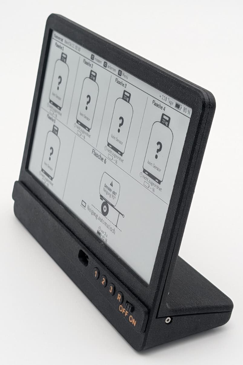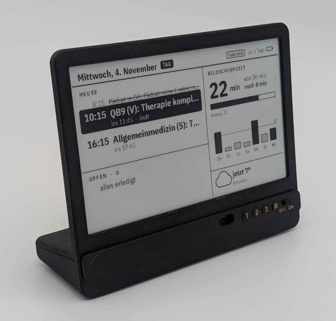
Over the last few years there have been phases when I used my calendar regularly and phases when I used it less. Since I am a rather unstructured person overall, a bit more order really helps me. So the idea was: what you see more often, you do more often. Until now, though, I only had my calendar on my phone. The obvious goal was therefore to give myself a physical display in my room. And while I was at it, I could show a few other things on it as well: tasks, weather and my phone usage.
The result is a small display without any backlight on my desk. In the morning it shows me what is coming up today, during the day my appointments, open tasks and how much time I have already spent on my phone, and in the evening when I should go to bed. Everything at a glance, without picking up a phone or laptop, and therefore without the risk of getting stuck somewhere on it.
The web part behind it is quickly explained. This article goes into more detail on two things that kept me busy much longer: the case, and the question of how long a device like this lasts on one battery.
Three Views for the Day
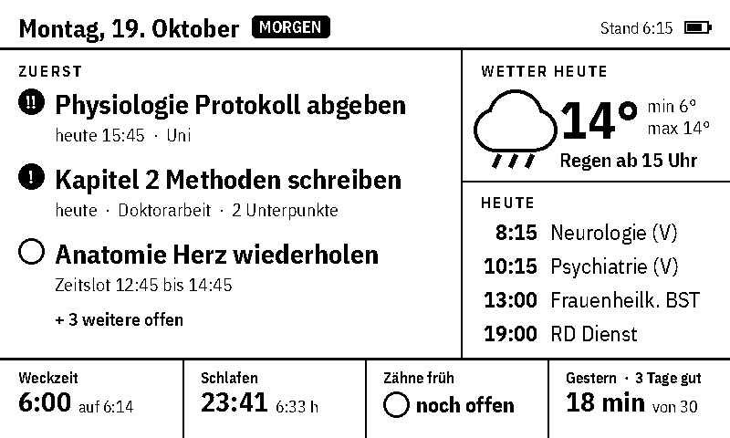
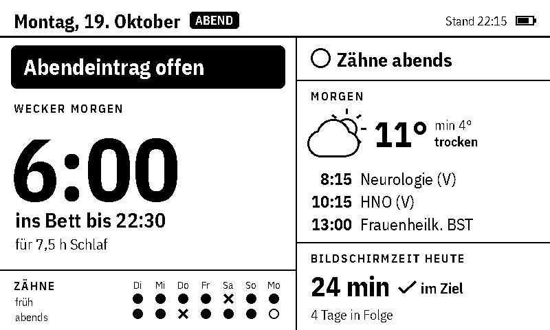
Depending on the time of day, the display shows one of three views.
In the morning, from the alarm time until 11 am: what to do first, today’s weather, today’s appointments, how long I slept and yesterday’s screen time.
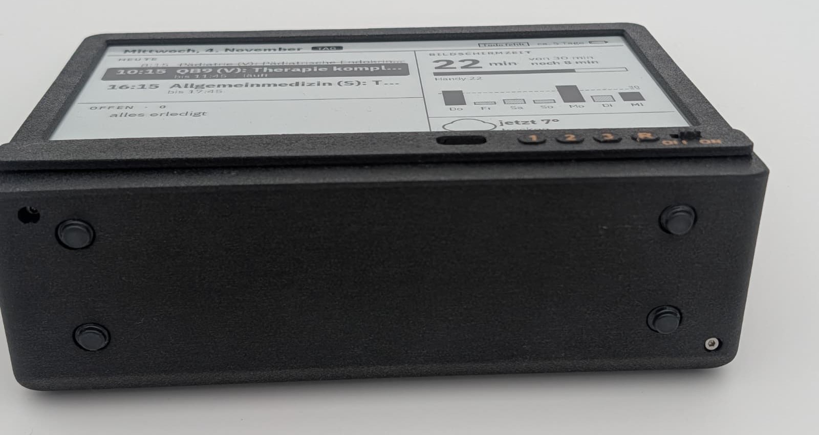
During the day, from 11 am to 9 pm: appointments, with past ones crossed out and the current one highlighted in black, open tasks, today’s screen time against my daily budget including the history of the last week, and the current weather.

In the evening, from 9 pm: whether I have already done my evening entry, a large alarm time for tomorrow and when I should go to bed, plus tomorrow’s weather and appointments.
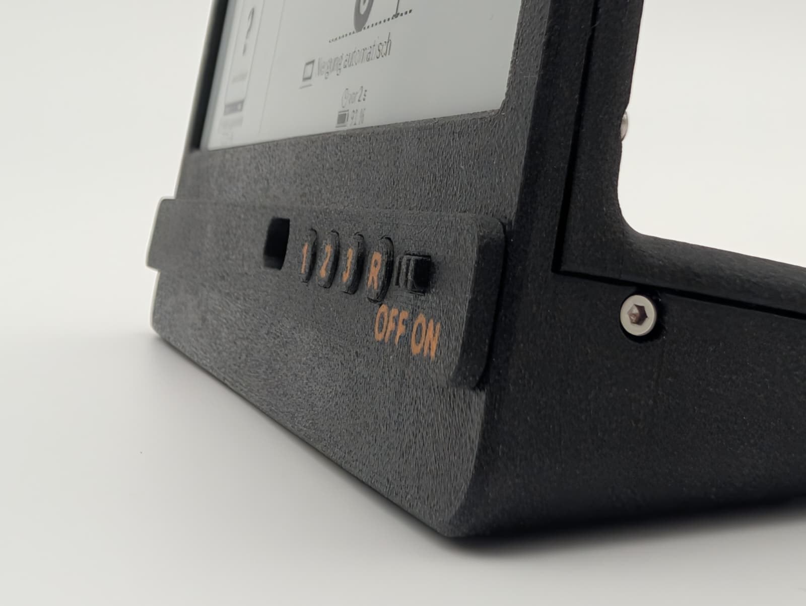
Below the display there are three buttons, a reset button and the on/off switch. Button 1 refreshes immediately, button 2 shows a status page for 30 seconds and button 3 starts the WiFi setup.
The Web Part in a Nutshell
All the logic lives on my home server. A small Python server runs there in a Docker container, collects the data and uses Pillow to draw a finished image from it: 800 × 480 pixels, 1 bit per pixel, exactly 48000 bytes. The data comes from
- Home Assistant: weather, alarm, bedtime and a few other values
- my self hosted Vikunja to do list: open tasks
- my calendars via iCal
- a small server of my own that adds up the screen time of my phone and PC
If a source fails, a note like “HA fehlt” (HA missing) appears in the top right corner.
The device itself is dumb, and that is on purpose. It wakes up, connects to the WiFi, fetches the image and goes back to sleep. To use as little power as possible, it relies on two tricks:
- ETag: The device sends the identifier of the image it is currently showing. If nothing has changed, the server only replies “304 not modified” and the display does not need to be redrawn.
- X Sleep: The server tells the device in a header how long to sleep. During the day that is 15 minutes, and it also wakes up exactly at the alarm time, at 11 am and at 9 pm. If night mode is active in Home Assistant, it sleeps through until the alarm.
With every request the device also sends its battery voltage. The server calculates the charge level and remaining runtime from it, which are shown in the header line. By the way, the voltage is measured before the WiFi is switched on, otherwise it sags under load. And to connect faster, the firmware remembers the channel and access point of the last connection.
The Case
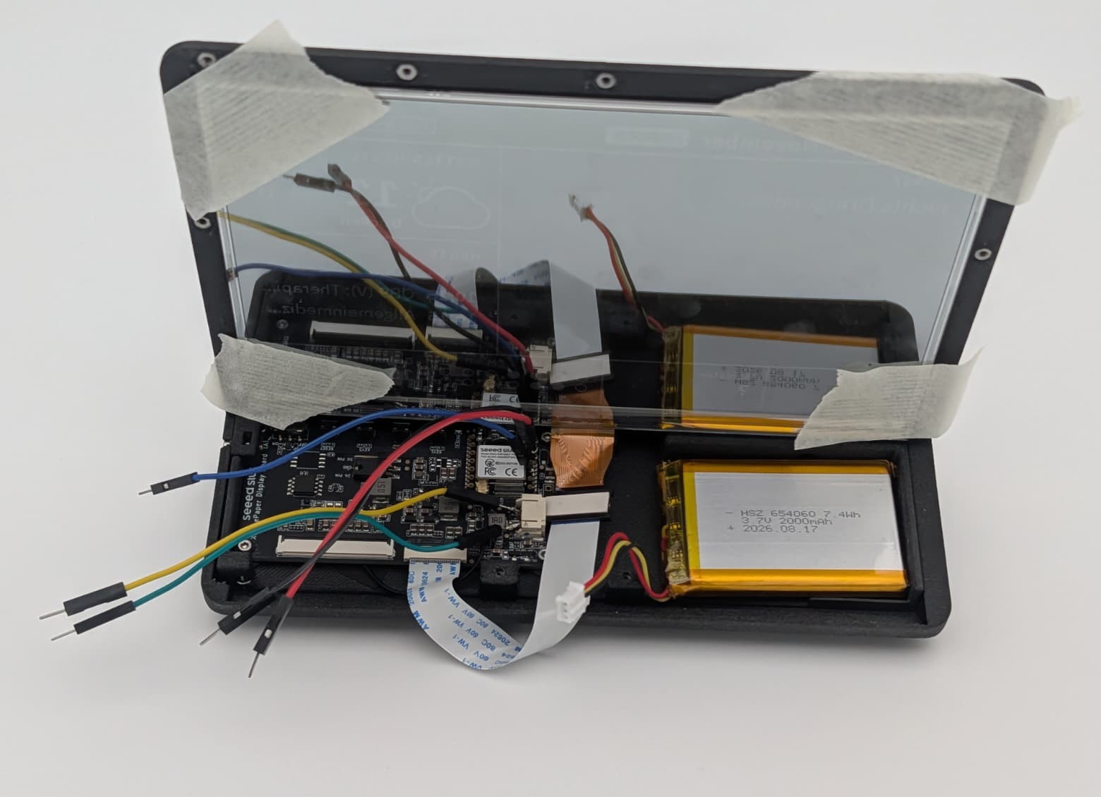
The basis is the TRMNL 7.5" DIY Kit from Seeed Studio. It contains the ePaper with 800 × 480 pixels, the driver board with a XIAO ESP32 S3 Plus, three buttons, a slide switch, USB C and a LiPo battery with 2000 mAh. Seeed offers a simple stand for it. For me it was too flimsy though, and I also wanted to be able to hang the display on the wall. The same device is also meant to hang on a tent pole as a gas level display at our summer camp. So I designed my own case that can do both.
Parametric in FreeCAD
I designed the case fully parametric in FreeCAD. All important dimensions live in a spreadsheet, all sketches are fully constrained. The template was the “TRMNL Stand with Buttons” case by Seeed Studio, from which I initially took the positions of the controls. From the fourth version on, the board dimensions come directly from its KiCad data: 80.0 × 41.23 mm, four holes with 2.5 mm diameter on a 74.90 × 36.21 mm grid. Buttons, USB socket and slide switch sit exactly where KiCad says they are, relative to the board edge.
Seeed does not provide a 3D model of the board. So I built a simplified dummy from the KiCad file with every component in its real position, plus the XIAO module, buttons, switch, flat cable connectors, battery and even the cables. A collision check then immediately shows where something does not fit. The renderings in this article were made with Blender from exactly this model.
Six Versions
It took six versions to get to the current state:
| Version | Main change |
|---|---|
| V1 | front housing in one piece, back cover, wedge base tilted 12° backwards |
| V2 | slide in tray from the front, round magnetic interface with detent joint for the holder |
| V3 | hidden seam, reinforced tray, all standard parts and the electronics in the model |
| V4 | board dimensions from KiCad, back cover includes the whole roof, base prints without supports |
| V5 | larger lettering, plain back cover as an alternative, play free joint |
| V6 | new holder for the tent pole, case as in V5 |
Construction
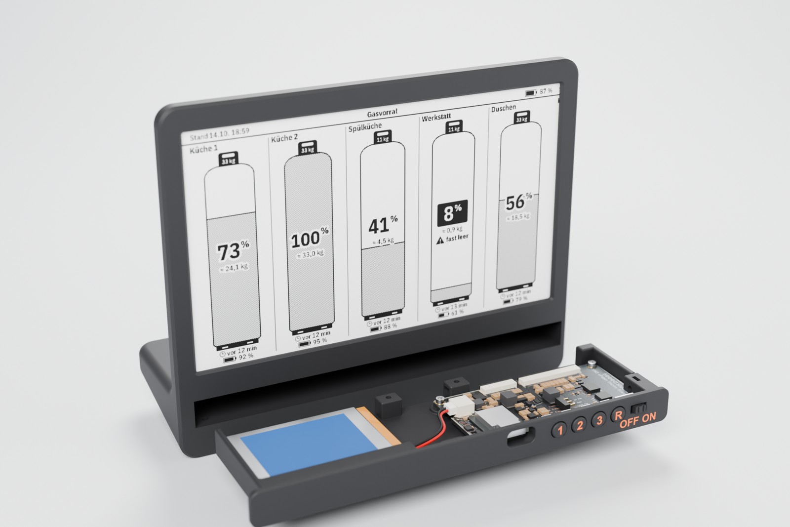
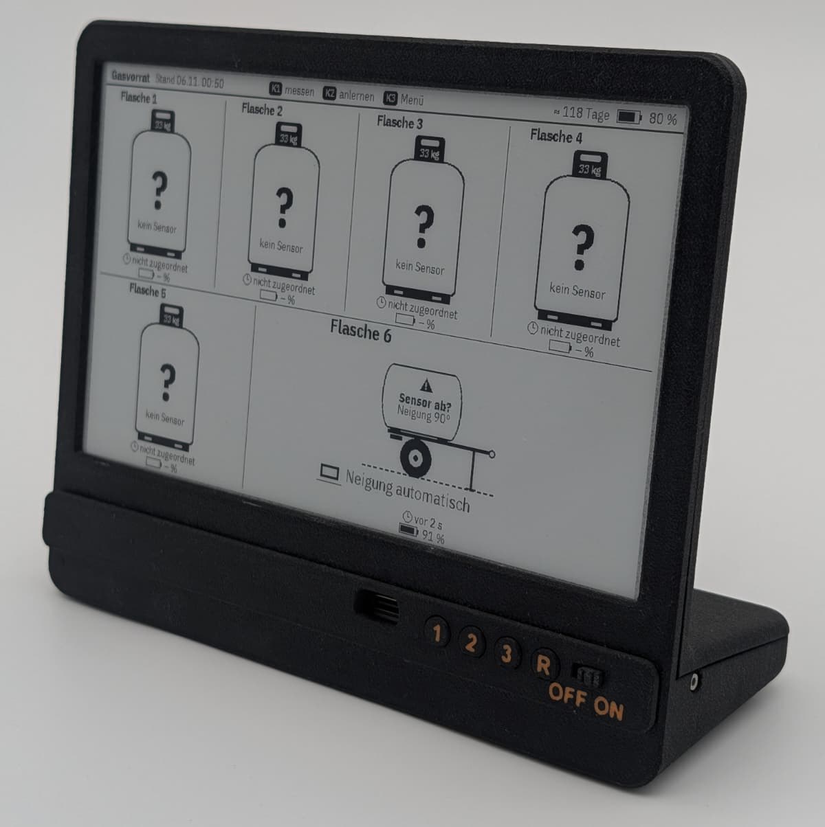
The case consists of just a few large parts:
- Front housing: one piece, printed lying on its front so the visible side comes out nice and smooth
- Back cover: includes the whole roof of the base, so the seam runs horizontally just below the rounding and is barely visible
- Tray: a sled that carries board and battery and can be pulled out from the front
- Bezel: at the front of the tray, with the button caps 1, 2, 3, R and the slider for the switch
The base is shaped as a wedge, so the display stands on the desk tilted 12° backwards. Inside, the rear wall of the base is a 45° ramp, so the front housing prints without any supports inside. Underneath there are four shallow recesses for rubber feet with 8 mm diameter. They are only needed when the device stands on a desk, on the wall or at the tent they stay empty.
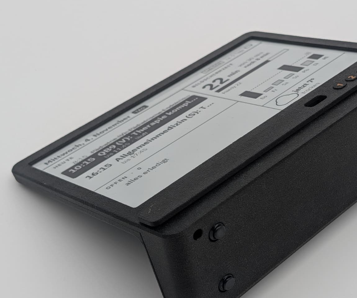
The Tray
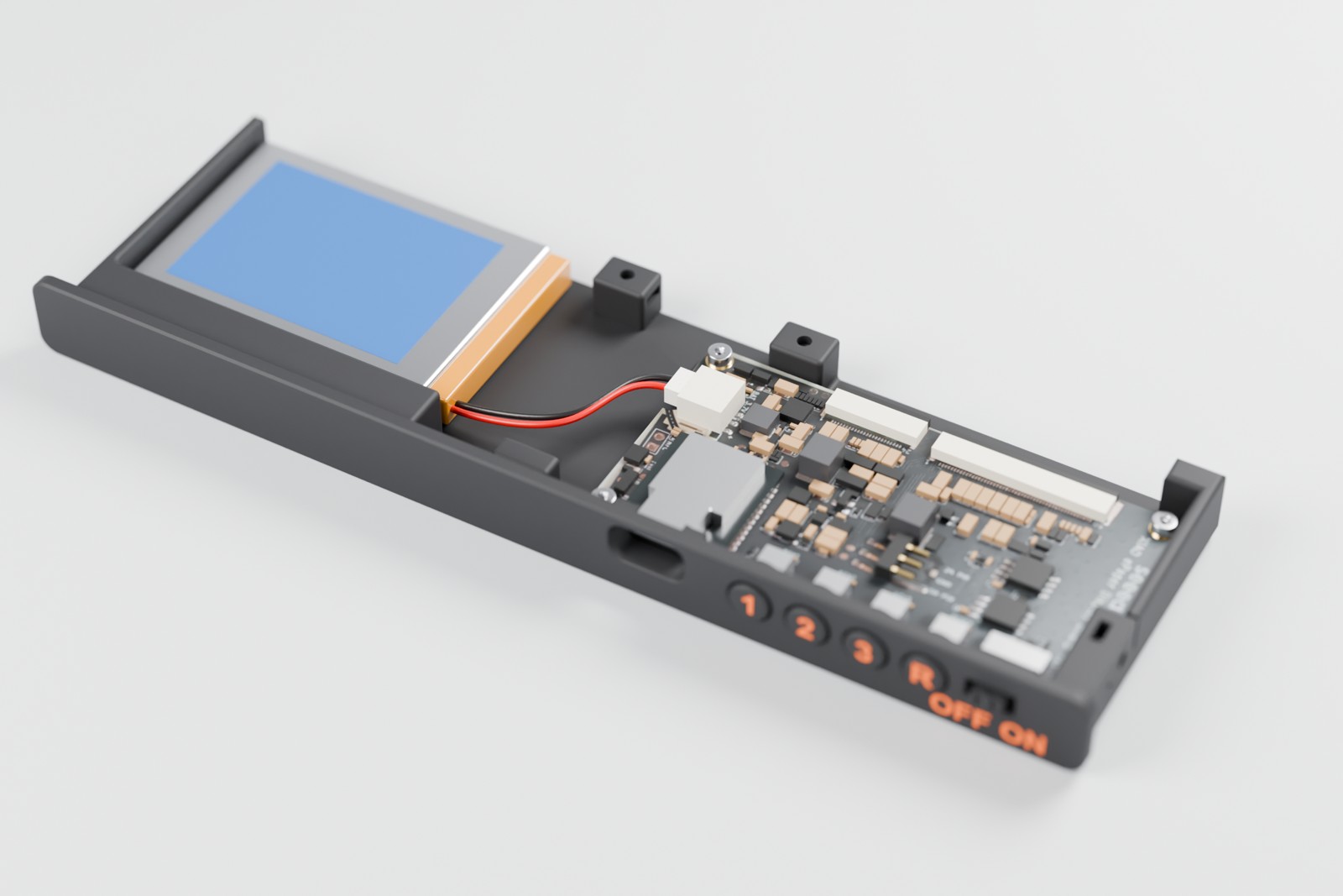
The electronics do not sit loose in the case but on a separate sled. The board rests on four bosses and is held with M2 screws, with the nuts sitting in pockets. Next to it the battery has its own compartment. A continuous bar in front of the battery acts as a stop, as a screw point for the bezel and as a nut pocket for one of the case screws at the same time.
The bezel sticks out of the case by 2.4 mm. The button caps have a flat so they cannot rotate. The labels are printed in orange as a second colour, and a small collar guides the USB plug.
Screwed, Not Glued
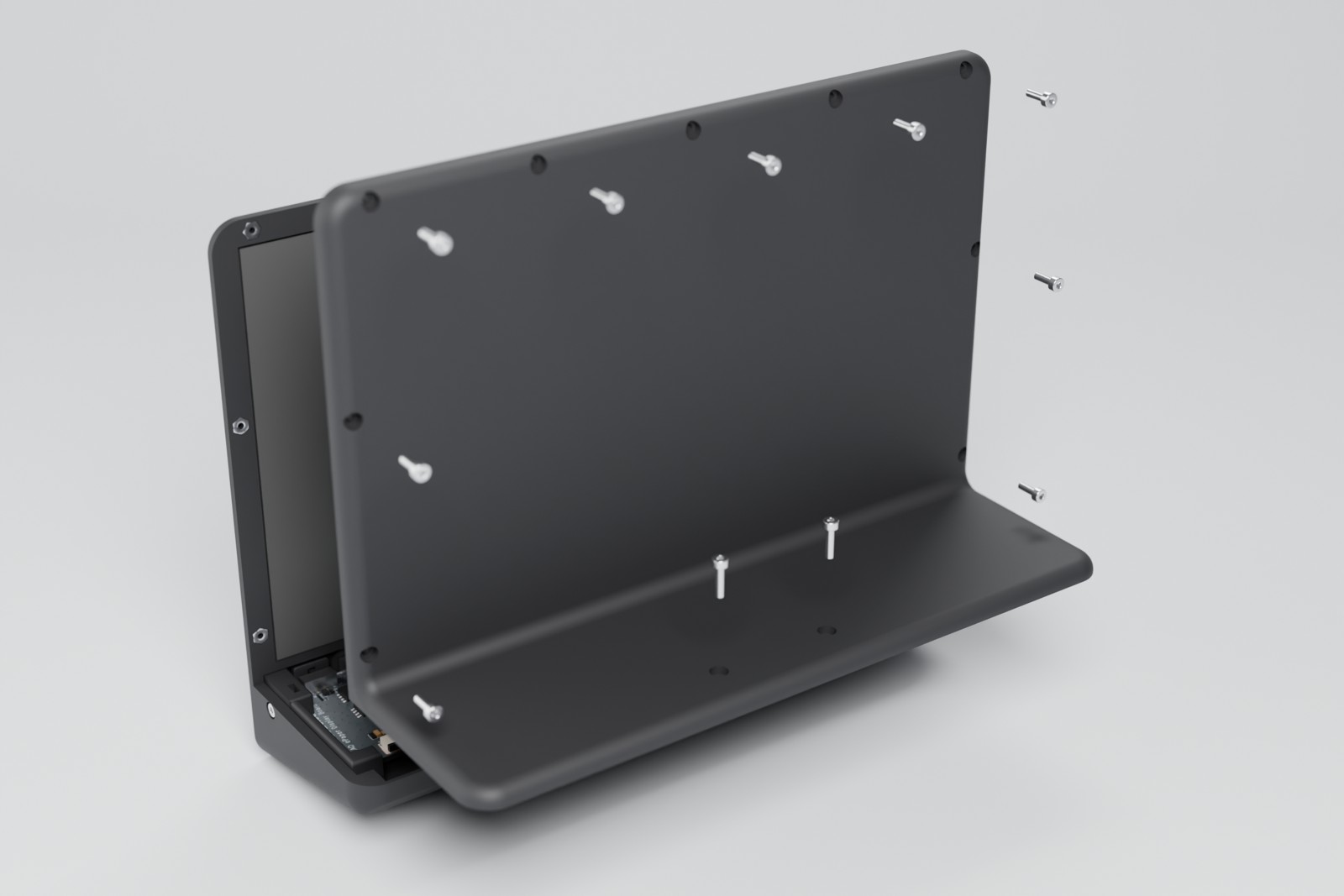
Everything is held together with M2 socket head screws and nuts, nothing is glued. The nuts sit in side slots, the heads in counterbores. This way the device can be opened at any time, for example to swap the battery or to measure the current.
Magnetic Holder with Detent Joint
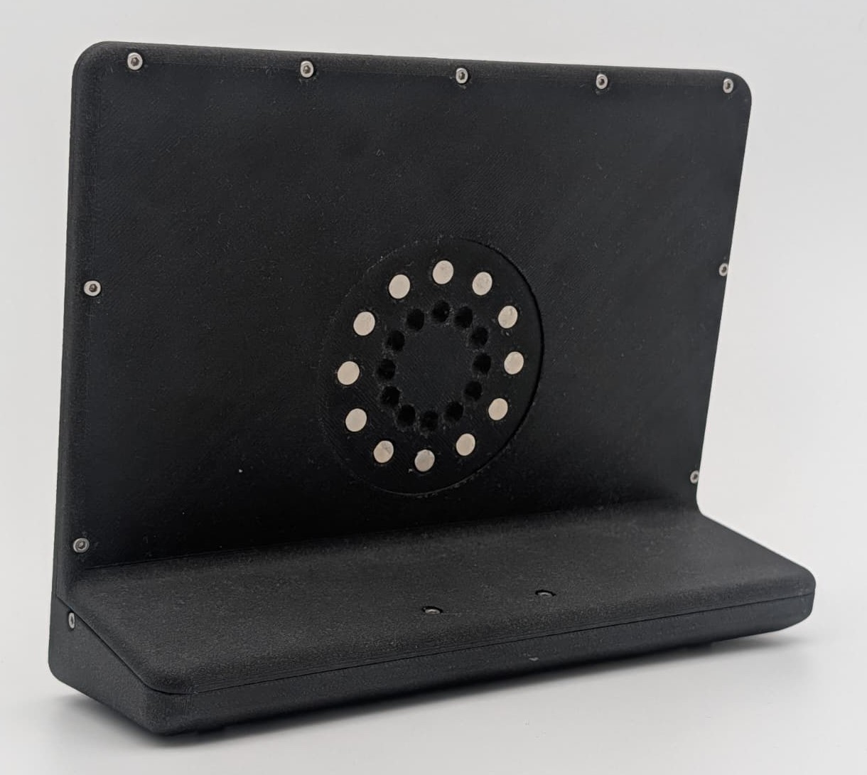
On the back there is the interface for a holder: a ring with 64 mm diameter with twelve stacks of two 6 × 2 mm magnets each, pressed in flush at 30° spacing, plus twelve cone sockets. The holder disc also contains twelve magnet stacks with reversed polarity and three cones that centre the display when you put it on. Thanks to the 30° spacing, the display can be attached in several orientations.
The holder itself has three parts: holder disc, joint and arm with wall plate. The wall plate is stuck to the wall with two strips of mounting tape.
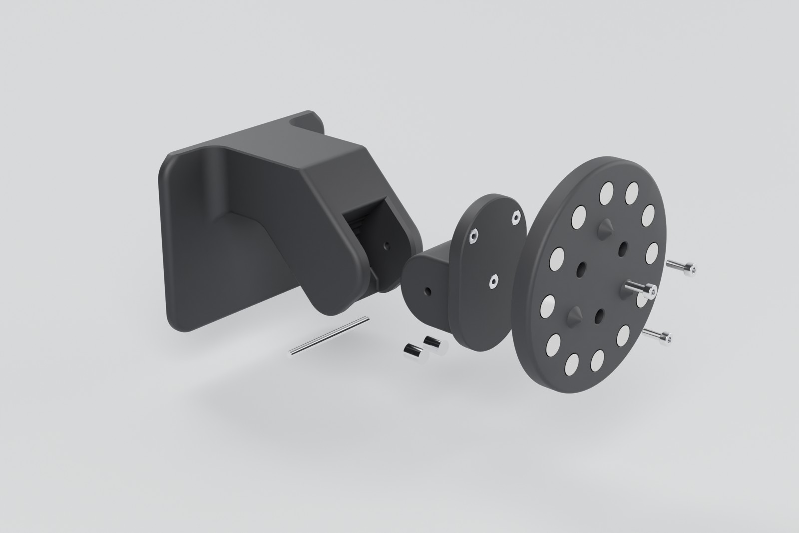
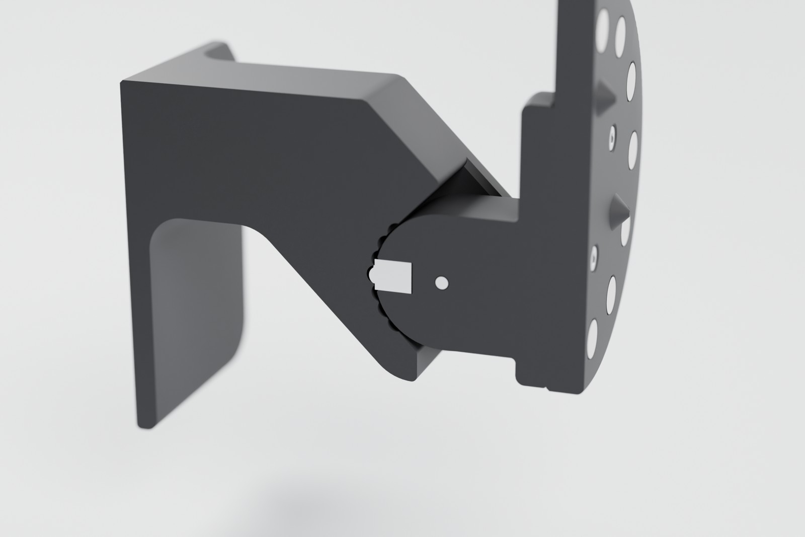
The joint clicks into place from −45° to +45° in 15° steps. For this, two ball spring plungers from Bambu Lab sit in the front face of the joint tongue and click into seven grooves in the arm. The two ball springs are offset against each other by ±1°. This way they are preloaded against each other in every position and the joint does not rattle. A steel pin with 2 mm diameter and 30 mm length serves as the axle.
In practice the display holds very firmly on the holder. For charging, it comes off with one move, but it does not come loose by accident.
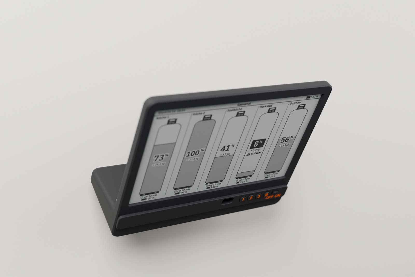
If you only want to put the display on your desk, print the plain back cover without the magnetic interface.
Measuring the Current
An ePaper only needs power while it changes its image, after that the picture stays without any energy. So most of the time the ESP32 can sit in deep sleep. How long the battery lasts therefore mainly comes down to two questions: how much current flows during sleep, and how much charge does each wake up cost?
The Setup
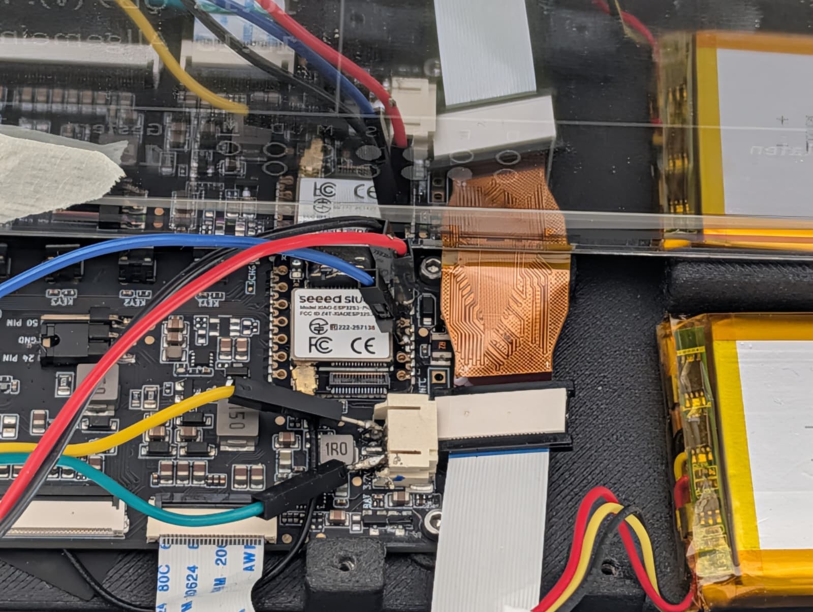
I measured with Nordic’s Power Profiler Kit II. It replaces the battery, supplies the device with 3.80 V, roughly the average voltage of a LiPo, and measures the current from below one microampere up to one ampere.
The PPK2 also has eight digital inputs. I connected one of them to GPIO8 of the XIAO, which the firmware sets HIGH while the device is awake. This shows exactly in the trace when the device is awake, and a small Python script can calculate the sleep current and the charge of every single wake phase from the exported CSV file.
The First Measurement: 15.5 mA While Sleeping
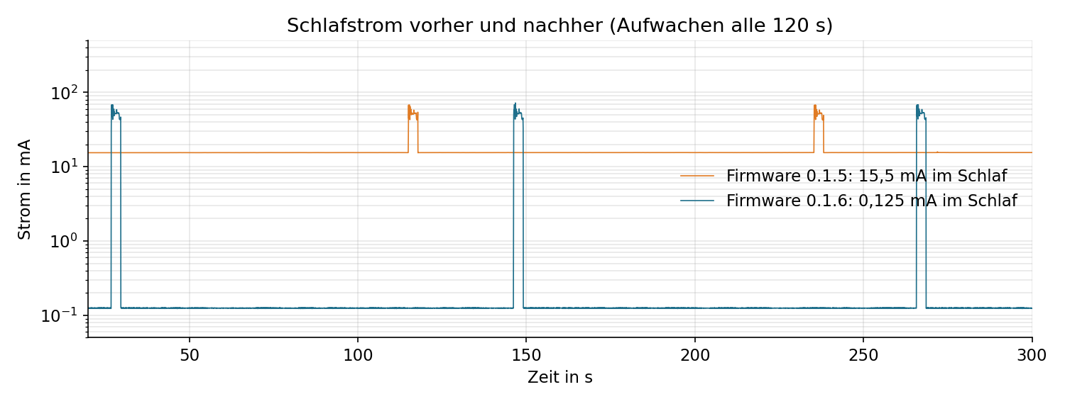
I did the very first measurement with the firmware of the gas display, on exactly this hardware. It was sobering: between the wake phases a constant 15.5 mA flowed instead of the expected little more than 0.1 mA. With 2000 mAh the battery would have been empty within a few days.
My first suspicion was that the ESP32 was not really sleeping. The raw data said otherwise though: the current in the plateau was completely flat, without the noise a running CPU produces. So the device was in deep sleep, and yet current was leaking somewhere.
To rule out the hardware, I wrote a minimal sketch that adds buttons, battery measurement, display and Bluetooth step by step and goes to sleep each time. Result: the hardware manages 0.125 mA, with the display connected. So the fault was in the firmware.
The Fix: Holding the Pins
The cause were pins that floated or kept being driven during sleep, mainly the display pins after using the SPI bus and the pin that switches on the voltage divider for the battery measurement. I did not narrow down which one exactly. The fix is the same for all of them anyway:
- End the SPI bus before going to sleep.
- Set the display supply (GPIO43), the battery divider (GPIO6) and all six display pins as outputs to LOW and hold them through sleep with
gpio_hold_en(). The order matters: first set LOW, then hold, so nothing floats in between. - Release the holds again when waking up.
- Configure the buttons as RTC inputs with pullup so they can wake the device.
After that the sleep current was 0.125 mA, a factor of 124 lower.
The Measurement with WiFi
For the actual room display, I put the firmware into a measurement mode: it wakes up every minute and alternately fetches a new image or gets the answer “not modified”. I measured for eight minutes.
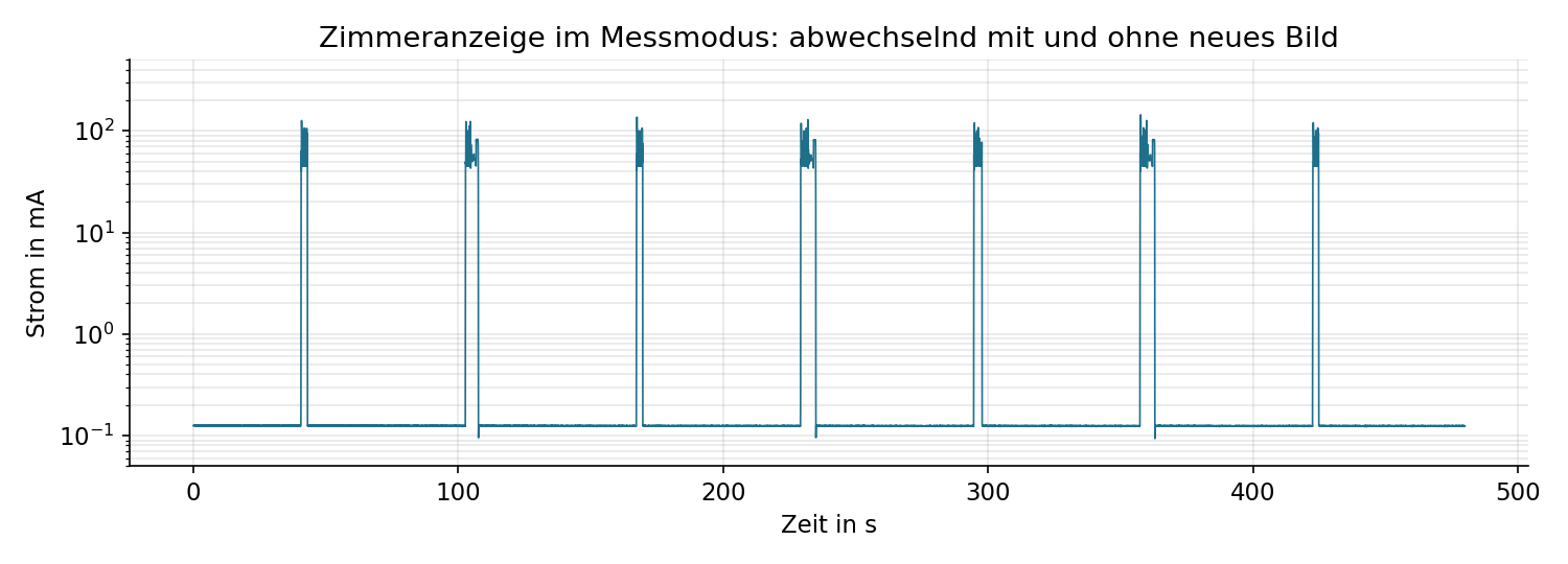
The first analysis produced a strange result: all wake phases looked like “with new image”. The reason: the WiFi briefly draws up to 380 mA while connecting, even without any display refresh. So the two types could not be told apart by their peak. Instead I separated them by their charge, and then it worked out.
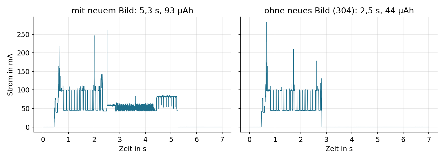
A wake phase with a new image looks like this: about 0.5 s boot, up to about 2.5 s WiFi and request with pulses around 100 mA, then about 2 s display refresh at 50 to 60 mA, and at the end just under one second at around 80 mA, probably saving the image to flash.
| measured | assumed before | |
|---|---|---|
| Sleep current | 124.6 µA | 40 µA |
| Wake up without new image | 44.2 µAh in 2.5 s | 120 µAh |
| Wake up with new image | 93.4 µAh in 5.3 s | 180 µAh |
| Peak current | up to 382 mA |
So the sleep current is the same as on the gas display with the fixed firmware. There is no leak anymore, but I had assumed it three times too low before and the wake ups almost three times too high.
How Long Does the Battery Last?
With 2000 mAh, of which I count 85 % as usable:
| Requests per day | with new image | Consumption per day | Runtime |
|---|---|---|---|
| 50 | 30 % | 5.9 mAh | 286 days |
| 70 | 10 % | 6.4 mAh | 264 days |
| 70 | 30 % | 7.1 mAh | 239 days |
| 70 | 60 % | 8.2 mAh | 209 days |
| 96 | 30 % | 8.7 mAh | 197 days |
Realistically there are about 70 requests a day, around 30 % of which bring a new image. That gives about 240 days, or roughly eight months. I find the split interesting: 42 % of the consumption goes to the sleep current, the rest mainly to setting up the WiFi connection. So if you want to squeeze out even more, the sleep current is a better place to start than the WiFi.
Material
| Part | Quantity |
|---|---|
| TRMNL 7.5" (OG) DIY Kit (display, XIAO ePaper board with XIAO ESP32 S3 Plus, 2000 mAh battery) | 1 |
| Socket head screw M2×4 (DIN 912) | 6 |
| Socket head screw M2×6 | 13 |
| Socket head screw M2×8 | 3 |
| Socket head screw M2×12 | 1 |
| M2 nut | 23 |
| Neodymium magnet 6 × 2 mm | 48 |
| Bambu Lab ball spring plunger 5 × 6 mm (FB004) | 2 |
| Steel pin 2 × 30 mm | 1 |
| Rubber foot 8 × 2 mm (optional, only for standing) | 4 |
| Mounting tape 20 mm | 2 strips |
| Filament ABS GF black and orange |
Microcontroller, board and battery are already included in the kit. If you print the plain back cover without holder, you do not need the magnets, ball springs, steel pin or mounting tape.
Assembly
- Put nuts into the blocks of the bezel, insert the slider and button caps from behind and screw the bezel to the tray with two M2×4.
- Place board and battery into the tray, screw down the board and plug in the battery.
- Slide the tray in from the front, secure it underneath with two screws and on the right side with one M2×6 through the case wall into the nose of the bezel.
- Insert the display, put on the back cover and screw it down with nine M2×6 and two M2×8 from the top into the roof.
- Holder: press in the ball springs, screw the holder disc to the joint, put the tongue into the fork of the arm and press in the steel pin.
Before the big print, the small test frame from the print files is worth it to check the fit of the display.
Build Your Own
I printed everything in black ABS GF with the lettering in orange via the AMS, on textured PEI. All print settings are saved in the Bambu Studio project, where all parts are already arranged sensibly on the plates. Test prints work well in PLA, PETG works too.
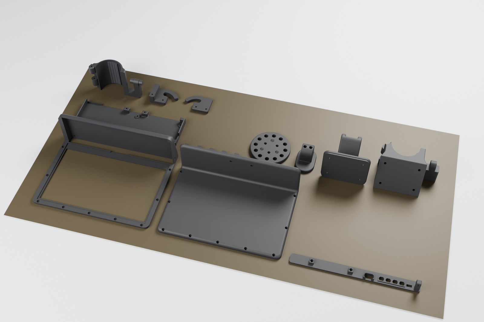
- Bambu Studio project with all parts and print settings (ABS GF)
- All individual parts as STL and 3MF with assembly instructions
- FreeCAD file, fully parametric
- Firmware and server of the room display
- Scripts and instructions for the current measurement
The case is licensed under CC BY-NC-SA 4.0. This means you may build, modify and share it free of charge, as long as you credit me as the creator, do not use it commercially and share your own modifications under the same license.
Firmware, server and measurement scripts are licensed under the MIT License. You may use, modify and share them freely, even commercially, as long as the license notice is kept.
If you have questions or need other file formats, feel free to write to me: loading …
Conclusion
What started as a quick idea turned into a more elaborate case after all, which kept me busy for a few evenings.