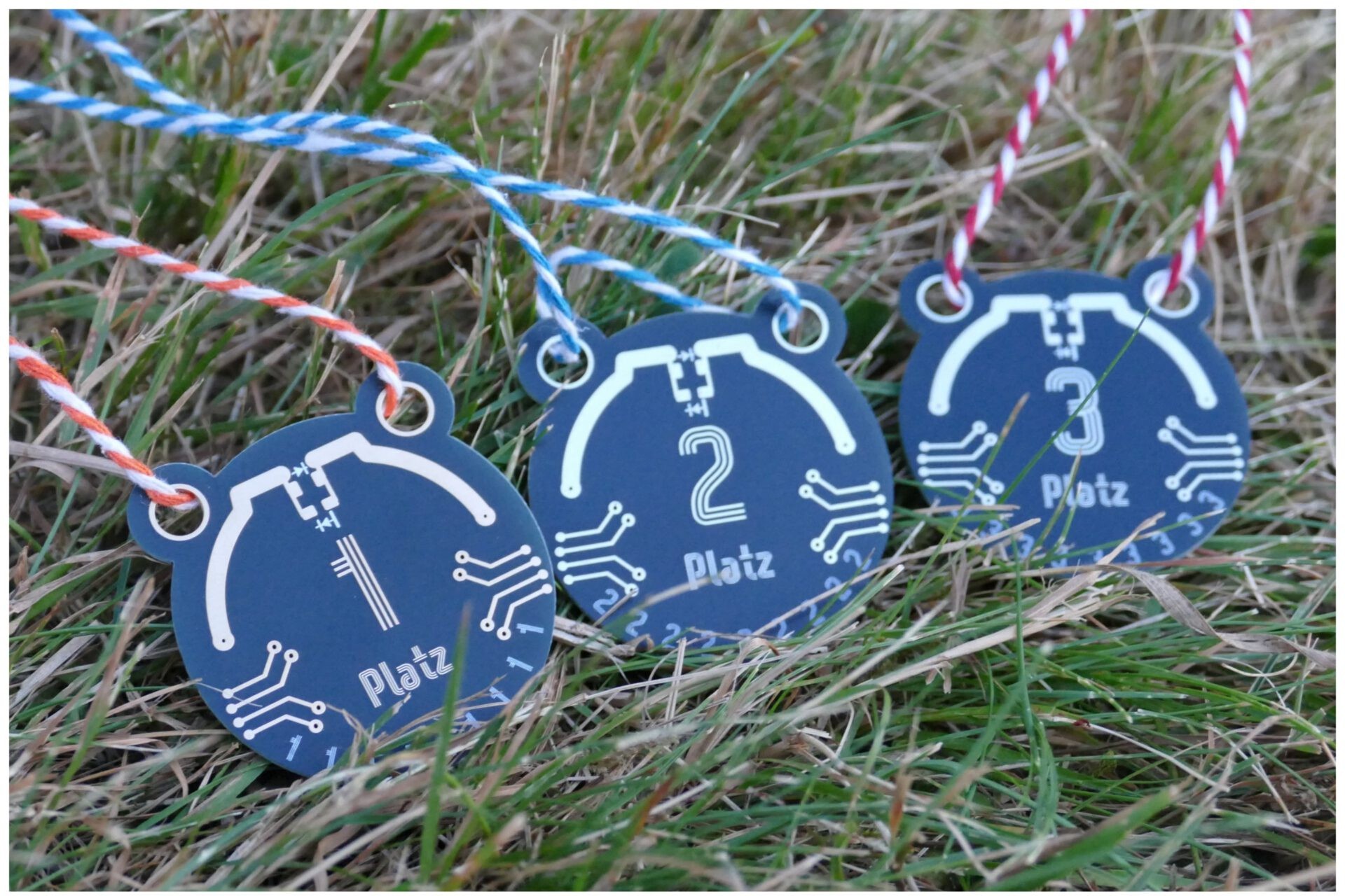
For a children’s summer camp with the theme agents and spies, we still needed medals. A good and above all cheap way to make custom medals is circuit boards. And if you are designing a circuit board anyway, it would be cool if the medal had an extra function. That is how the idea came up to build a WiFi detector into the board, just like real spy gadgets. Apart from the medal itself, all you need is an LED and a diode. What started out disguised as a quick idea soon turned into a nice project spanning two evenings.
How It Works
Thankfully, I did not have to start from scratch. Another camp counselor had already done some groundwork and designed a concept for the look of the medal: three variants for gold, silver and bronze, with matching motifs ranging from a radar to a radio symbol to a laurel wreath with an antenna. My idea was to combine this look with a real function. The basic idea is essentially a crystal radio, just without tuning to a station: a folded dipole on the circuit board picks up the 2.4 GHz WiFi signals directly, a very fast diode in the middle of the antenna rectifies this tiny AC voltage, and an LED right next to it makes the result visible.
Assembly
Fortunately, the assembly itself is the short part. All you need is the following:
- Circuit board
- Diode (1N5711W)
- LED (LTST-C150KRKT)
- Soldering iron with a fine tip
- Solder
- Tweezers
- (desoldering pump or desoldering wick if needed)
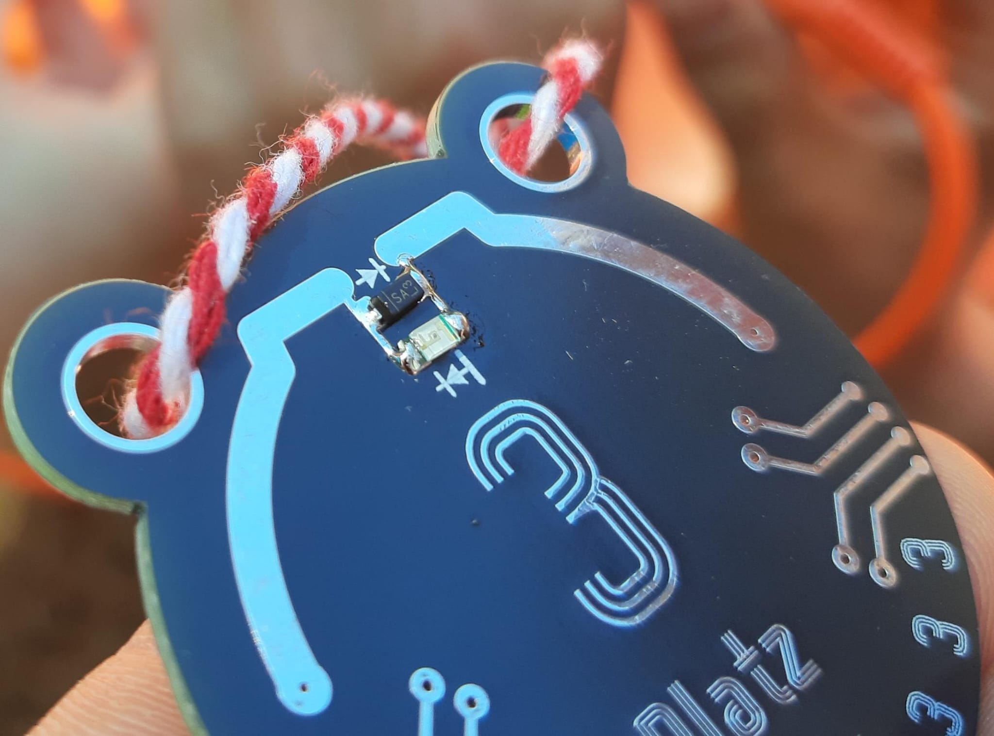
When assembling with children, it has proven useful to take only one component at a time out of the SMD tapes. First, wet one pad with a bit of solder. Then heat the contact again with the soldering iron in one hand, and with the other hand use the tweezers to push the LED or diode into place. Afterwards, heat the other pole and solder it down. Then repeat the whole thing for the second component. In principle it does not matter whether the LED or the diode is “on top”. Polarity does not matter either, as long as the LED and the diode are mounted in opposite directions. Here you can see a successful build.

Demo
The most exciting moment is of course the first test.
Even though antennas sometimes seem like black magic, even the best antenna design cannot work miracles. In the video, the LED only lights up once the medal is held within a few centimeters of the access point’s antenna. That is simply due to the available energy; WiFi transmits at very low power anyway. Routers, access points and phones in hotspot mode are well suited for testing, as long as they use the 2.4 GHz band. Many microwave ovens are not perfectly “sealed”, and since they use the same frequency, the medals light up near them.
In a running microwave, even medals without an LED light up briefly, once xD
The Technology
If you have read this far and want to know what is actually inside the board, here comes the technical part.
I chose 2.4 GHz rather than 5 or 6 GHz, even though up to ten times the EIRP may be transmitted on 5 or 6 GHz in some cases. For one thing, higher frequencies experience a (quadratically) higher free space path loss, i.e. with the same antenna gain, an antenna at 5 GHz receives only about 25 % of the energy of a 2.4 GHz antenna. In addition, a higher carrier frequency also requires faster diodes with lower capacitance. These are not only more expensive, but also increasingly less available in packages that are easy to solder.
The most naive approach to calculating the antenna would be:
$$ \lambda = \frac{c}{f} = \frac{3*10^8 \frac {m}{s}}{2.45\ GHz} = 122\ mm $$For one arm of the dipole that would be $ 122 \ mm * 0.25 = 30.5\ mm$. However, the antenna does not exist as an ideal conductor in a vacuum. Like all real conductors, the antenna has a shortening factor, and the circuit board substrate, at about 4.5, has a much higher relative permittivity than vacuum. Overall this results in a shortening factor of about 0.77. So the calculated length is:
$$ 30.5 \ mm * 0.77 = 23.49 \ mm $$I do not know this value exactly, though, because I skipped a defined impedance stackup to save costs. In addition, the antenna is electrically shortened by the self capacitance of the LED and the diode. To compensate for this, the antenna would have to be lengthened again. Here I only estimated and rounded up to 25 mm.
The attentive reader may also have wondered why an extra diode is needed at all, when LEDs, as the name suggests, should already do the job. The answer lies in the junction capacitance. According to its datasheet (where it is called CT), the diode has at most 2.0 pF at 0 V and 1 MHz, and according to the curve it drops even further towards 0.4 to 0.8 pF under reverse voltage. At 2.45 GHz this gives a reactance of around 33 ohms, i.e. in the same order of magnitude as the radiation resistance of a half wave dipole of about 60 to 90 ohms. The diode is therefore high impedance and acts as a real nonlinear switching element instead of simply shorting the antenna. The LED, on the other hand, is not built for this: its junction area is optimized to emit as much light as possible and therefore typically has a much larger capacitance somewhere in the range of ten to several tens of picofarads. Assuming 20 pF as an example, the reactance at 2.45 GHz is only about 3 ohms. That is far below the radiation resistance of the antenna and would practically short circuit the RF signal at the feed point instead of converting it into a usable DC voltage.
Secondly, there is the forward voltage. According to the datasheet, the 1N5711W already conducts at about 0.41 V typical at 1 mA, while a red or hyper red LED usually only carries significant current from about 1.6 to 2 V. The tiny AC voltage that a small unmatched PCB antenna picks up from ambient WiFi is roughly estimated to be only in the range of a few tens to perhaps a few hundred millivolts peak. That is enough for the Schottky diode, but never for the LED alone. Without the fast, low impedance diode, practically never enough voltage would build up for anything to happen at all. As a small bonus, the diode also provides a protective function: according to the datasheet it has its own guard ring construction, and its permissible reverse voltage of 70 V is far above what an LED can normally tolerate in reverse. So in the anti parallel circuit, the diode also catches the voltage peaks that could otherwise damage the LED.
The width of the antenna was a deliberate decision as well. A wide trace instead of a thin wire lowers the quality factor of the dipole. A lower quality factor means more bandwidth at a somewhat lower peak impedance, so the antenna remains reasonably well matched even if the resonance shifts slightly due to manufacturing tolerances, calculation tolerances or the component capacitances. A nice side effect is that the larger surface also reduces the losses caused by the skin effect, so the ohmic resistance decreases.
And the fact that the dipole can be bent to follow the round medal design without losing much gain is consistent with what a report titled “Effects of Meandering on Dipole Antenna Resonant Frequency” shows: bends mainly change the electrical length for the same physical size, the resonant frequency shifts somewhat, but the radiation efficiency stays good as long as you trim back to the target frequency afterwards. This applies well to single, moderate bends like our arc of about 54 degrees; with very tight, repeatedly folded meander shapes, the loss of gain becomes more noticeable. For a medal that you hold up to a phone from changing angles anyway, a somewhat more rounded radiation pattern is more of an advantage than a disadvantage.
For the diode I chose a 1N5711W from Diodes Incorporated in a SOD123 package; an LED with the lowest possible capacitance and a size that is still easy to solder by hand completes the assembly. In the end, everything had to fit into the small round area of the medal, fifty by fifty millimeters, without the antenna or the components colliding with the holes for the lanyard.
The circuit boards were manufactured externally, with a different surface finish depending on the placing: ENIG for first place, immersion silver (lead free) for second place and partly unprotected copper surface for third place. Unfortunately, my PCB manufacturer does not offer bare copper surfaces. So for third place I also ordered them with lead free tin. Afterwards I removed the tin layer again with hydrochloric acid. Then the boards were neutralized in a sodium bicarbonate bath and protected against oxidation with a layer of resin. Since the process takes a lot of manual work, unfortunately I did not have enough time to do this for all of them.
Build Your Own
I think the circuit is ideal if you want to solder with people for demonstration purposes. Depending on prior experience and guidance, you are done in about 2 minutes. The circuit is easy to understand, yet offers practically unlimited depth to dive into. It is also very cheap. For a total of 300 boards I paid the following:
- 25 € each for 100x second and third place (lead free tin plated) + 38 € for first place (ENIG)
- 300 diodes (1N5711W) about 30 €
- 300 LEDs (LTST-C150KRKT) about 30 €
This results in the following prices per kit
300 pieces => 50 ct each
500 pieces => 30 ct each
If you have questions or need files, feel free to write to me: loading …
Conclusion
In the end, even a small evening project contains quite a bit of antenna magic. Since I was studying for my amateur radio license at the time, I found it a nice excursion. The children at the camp had their fun too, and proved that when it comes to hands on building, a young pair of eyes for the polarity markings on the tiny components helps more than all the antenna knowledge in the world.