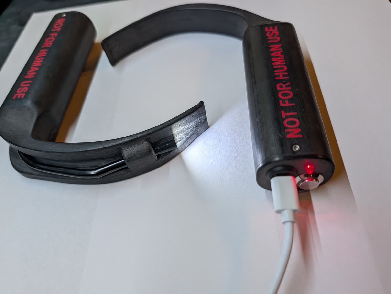
I am involved in the AG EH MED e.V. Our association teaches first aid courses, and because a large part of our target group are medical students, we additionally offer optional extra topics that do not fit into a normal first aid course. One of them is a lesson on airway management, in which participants learn the basics of securing the airway, from the Guedel airway to the endotracheal tube.
When demonstrating and explaining endotracheal intubation, however, we always had the same problem: even in small groups of five to eight participants, it is hard for everyone to see something at the same time. With a classic laryngoscope, only one person can look into the throat. Ideal would be a video laryngoscope with a large screen that everyone can watch.
First Tests with the AirAngel
A big thank you at this point to Sebastian from the AG. He built an AirAngel video laryngoscope. This is a non profit project that aims to make video laryngoscopes accessible all over the world using 3D printing and a cheap endoscope camera, thereby helping to prevent complications during intubation. The basic idea: you print a laryngoscope blade, insert an endoscope camera for about 15 €, like the ones used for pipe inspection, connect it to your phone with a USB cable and use the phone as a screen.
That worked great for us in the AG. But I thought you could go one step further. To me, the AirAngel laryngoscopes were still considerably bulkier than normal laryngoscopes, and the cable to the phone always bothered me a bit. That is how the idea came up to have another go at it myself.
My First Own Design
The camera
I also chose an endoscope camera, but a variant that transmits the image via its own WiFi hotspot, which the camera opens itself. It is still relatively cheap, about 50 € per endoscope, and all the electronics with battery, lighting and radio are already there. I used the WiFi endoscope camera from OOZAKA with a 5.5 mm camera diameter. In principle, though, any similar WiFi endoscope camera should work, as long as the electronics fit into the housing. You then view the image in the WiFi Look app on a phone or tablet.
Taking the endoscope apart
It’s what’s inside that counts
The endoscope itself is already very compactly built. Still, its plastic shell takes up unnecessary space and is superfluous, because the electronics are supposed to go directly into the laryngoscope anyway. So the first step was to open up the endoscope.
After building five laryngoscopes I can say: the best way is to carefully score the ultrasonic weld of the housing all the way around with a knife and then pry it open. Preferably from the side with the switch, because that way you do not risk damaging the battery. Inside the endoscope is an 18650 lithium ion battery with 2600 mAh. Handle it with care: do not stab it with the knife, do not crush it and do not create any short circuits. The battery is connected to the board via a small plug. Unplug it before doing any further work.
After that, the electronics can be taken over completely. I then shortened the camera cable. Do not use fine flush cutters for this, because the cable contains a hardened wire as a flexible guide, and that will damage the cutting edges.
Assembling the first version
The housing of the first version consists of two parts: the laryngoscope with an attached electronics housing, and a lid. I printed both on my Bambu Lab X1C in black PLA.
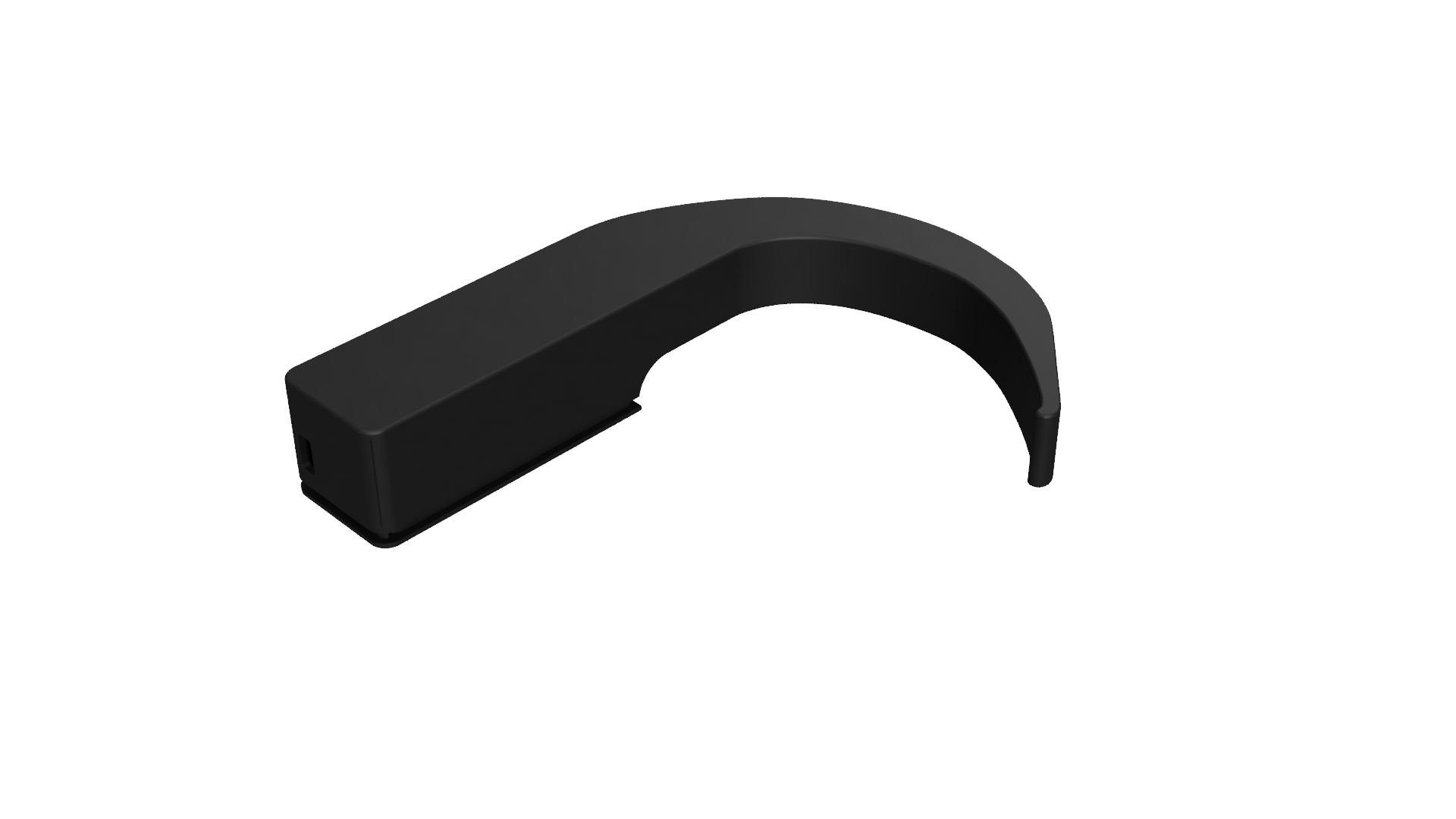
In the first version, the electronics were simply placed into the box and fixed with hot glue, in such a way that the switch and the brightness wheel could still be operated.
The camera is inserted from the front through the fixing hole at the tip of the blade, and the cable is routed through the channel into the housing. There it is soldered back onto the plug to the circuit board. After switching it on for the first time, you grab the camera module with pliers or a needle holder and rotate it until the image is straight.
With that, the goal was achieved: wireless operation and a much slimmer front part of the laryngoscope.
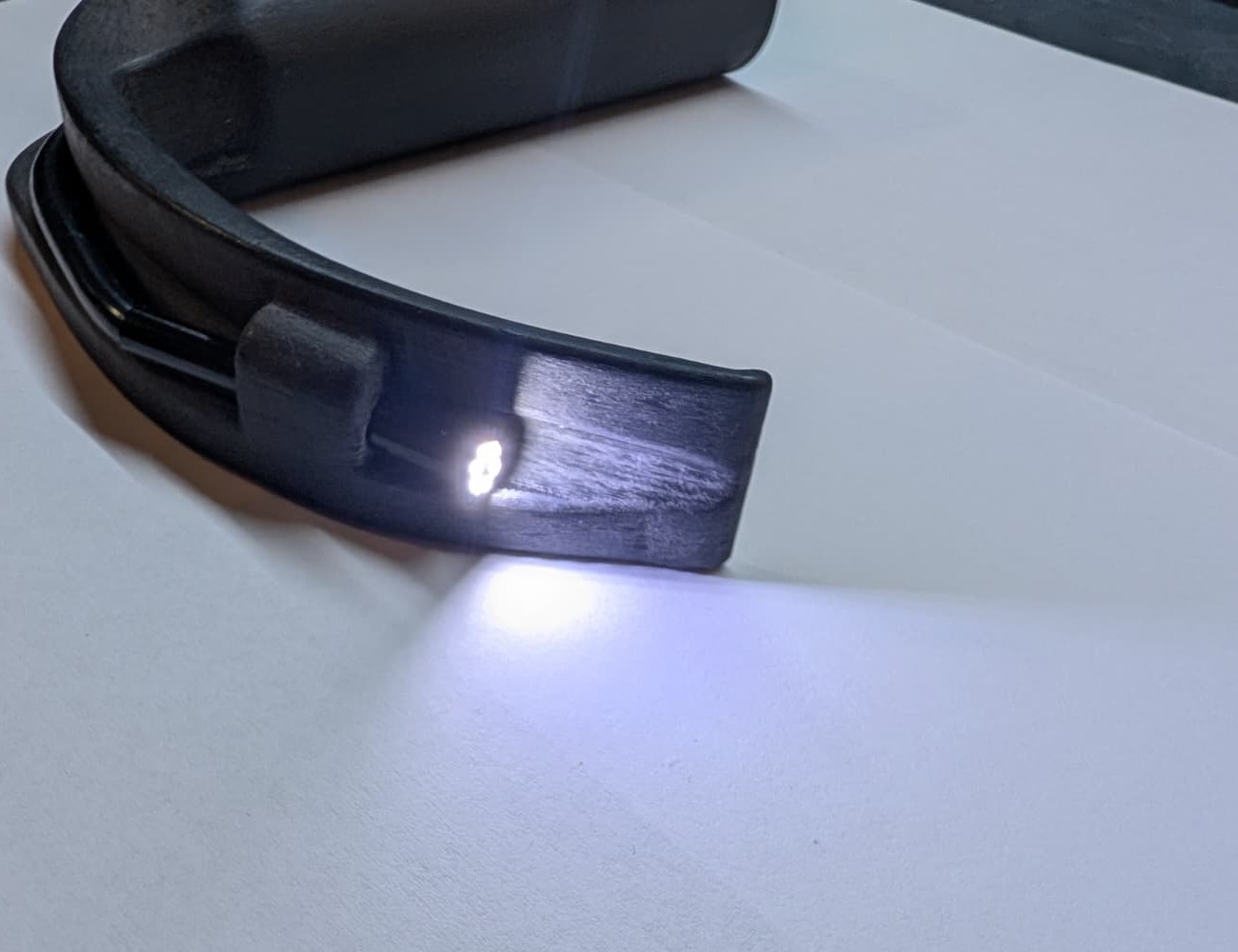
Version 2
If it’s written on it, you don’t have to explain it
Even though the first version worked, it did not sit well in the hand because the box was too angular. In everyday course use it also turned out that it was not yet user friendly enough:
- Every time, we had to explain what the camera’s WiFi hotspot is called and which app you need on your phone or tablet. Nobody remembers that. So it should be printed directly onto the laryngoscope.
- Everyone always turned the LED lighting up to maximum brightness. So the wheel is not needed at all, and the brightness can stay fixed at maximum.
- For some of our instructors it was apparently necessary to also write on it that this is not a medical device and that self intubation carries risks. Greetings to Maurice 😉
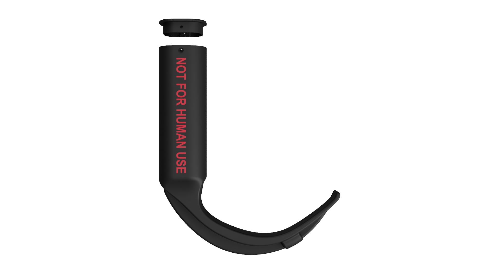
I also decided to screw the lid shut, to replace the board’s status LEDs with my own LEDs, and to place these together with an on/off switch and a USB C charging port directly in the lid. And instead of just one shape, there are now two blades: a curved one, which I modeled roughly after the Macintosh blade, and a hyperangulated one.
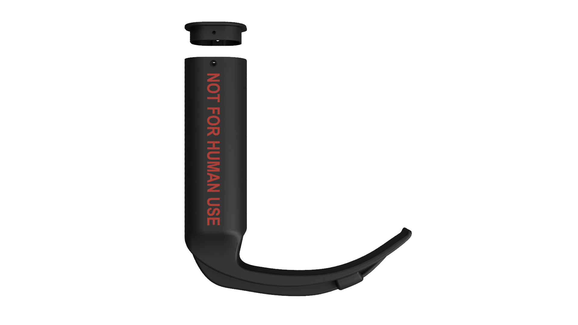
One side of the handle says NOT FOR HUMAN USE, the other the name of the app. The WiFi hotspot has the same name, just with the model number appended. That way everyone immediately knows what to connect to.
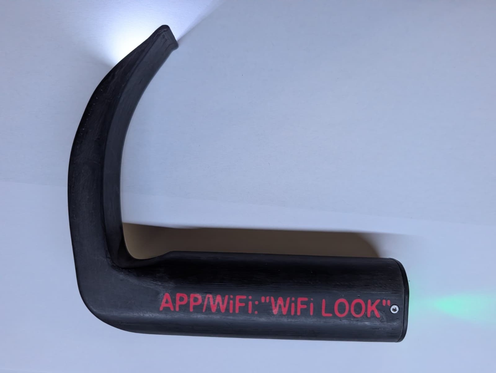
The hyperangulated blade is curved much more strongly. This shape is common especially for video laryngoscopes, because it lets you look around the corner without having to align the axes of mouth, pharynx and larynx as much.
Printing and post processing
This time I again used black PLA (more on that in the conclusion) and printed the lettering directly in red PLA. Afterwards I sanded the parts with 80 and 220 grit sandpaper and then very briefly heated the surface with a Bunsen burner, well under a second per spot. This melts the surface minimally, and the plastic loses its matte, sanded look. The surface becomes much smoother and glides much better in the training manikin.
Please be careful here: PLA softens at low temperatures and can warp or catch fire if heated for too long. So better pass over it several times briefly than once for too long.
The lid is secured with two M2 × 4 mm screws. The lid has recesses for M2 nuts, which act as threads.
Electronics
The hardware and the basic assembly have remained the same compared to the first version. What is new is that the switch, the charging function and the status LEDs are now tapped from the board and routed to the outside into the lid.
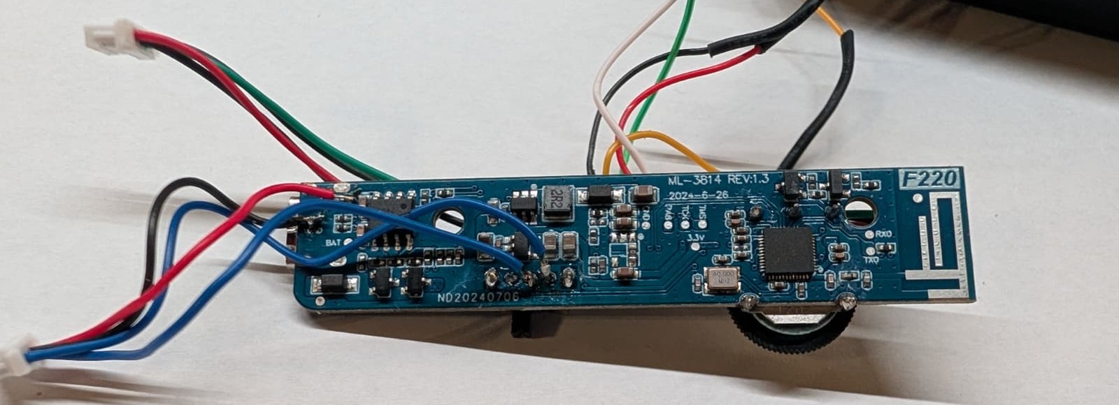
The two blue wires are soldered to the contacts of the original slide switch. The original switch remains on the board but is set to OFF. In parallel, the lid holds a latching metal push button with 12 mm diameter, a high cap and a normally open contact. In principle any switch will do here, as long as it latches and is not a momentary button that only switches while you hold it down.
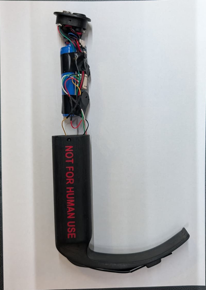
The other two wires are soldered to the labeled test pads for VCC and GND and lead to the USB C charging port in the lid. I removed the board’s original SMD LEDs and also routed their pads to the outside via wires. So that the lid together with the electronics can be pulled out of the handle, all wires end in a JST SH plug. The matching counterpart sits in the lid.
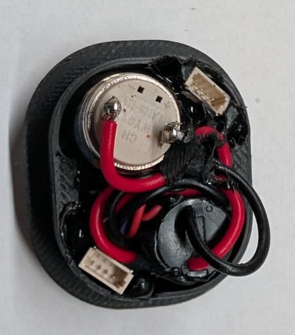
Everything is glued into the lid with black hot glue. The black material prevents light from the LEDs from scattering through the glue to the outside, looks much more professional and makes the whole thing very robust.
The lid also holds one red and one pure green 3 mm LED. They indicate the state of the laryngoscope:
- Red: battery is charging
- Green while charging: battery is full
- Green blinking during operation: hotspot is open, but no device connected yet
- Green steady during operation: phone or tablet is connected
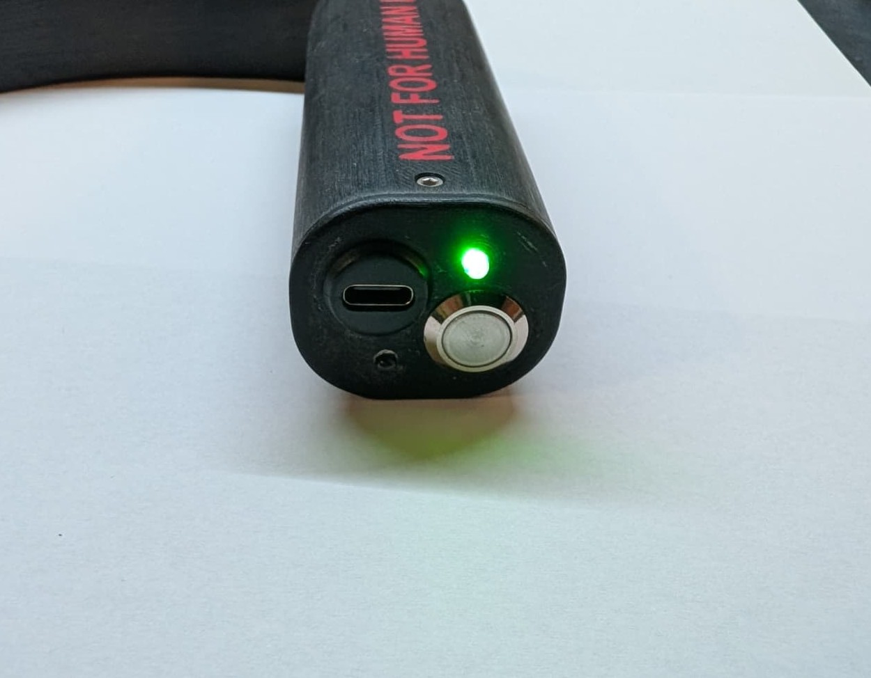
So that the LEDs do not draw too much current from the board’s 3.3 V, each LED gets a series resistor. It is calculated from the supply voltage $U_B$, the forward voltage of the LED $U_F$ and the desired current $I_F$:
$$R = \frac{U_B - U_F}{I_F}$$For the red LED with $U_F \approx 2.0\ \text{V}$ I used 150 Ω, which gives about 9 mA. The pure green LED has a much higher forward voltage of about 3.0 V, leaving only 0.3 V for the resistor. With 33 Ω, about 9 mA flow here as well.
This is what it looks like when you pull the lid together with the electronics out of the handle. The board and the battery sit together in a compact package that slides into the handle.
Build Your Own
Important: This is not a medical device. The laryngoscopes are intended exclusively for teaching on training manikins and must not be used on humans. That is exactly why it is written on them. In addition, the image is transmitted via WiFi. In practice this was never a problem for us, but a wireless connection can always lag or drop out, and that is not an option on a human.
Material
- Body and lid from the 3D printer
- WiFi endoscope camera, mine from OOZAKA with a 5.5 mm camera head
- Latching switch or push button, mine a 12 mm metal push button with a high cap and normally open contact
- USB C panel mount socket for charging
- One red and one pure green 3 mm LED
- Resistors with 150 Ω and 33 Ω
- JST SH plugs and sockets
- 2 screws M2 × 4 mm and 2 nuts M2
- Thin stranded wire
- Black hot glue
- Sandpaper with 80 and 220 grit
- Bunsen burner or gas torch for smoothing
- Soldering iron, a knife for opening the endoscope, and pliers or a needle holder for aligning the camera
Print settings
- Layer height 0.15 mm
- 12 wall loops
- 30 % infill
- With supports
- Printed lying down, so that the side with NOT FOR HUMAN USE faces up
For use in teaching I recommend GF ABS instead of PLA; the reason is in the conclusion.
Files
- Version 2 complete, both blades with lids and colored lettering: Bambu Studio project as 3MF
- Version 1: body as STL, lid as STL, Fusion 360 project
- Version 2 with Macintosh blade: body as STL, lid as STL, Fusion 360 project
- Version 2 with hyperangulated blade: body as STL, lid as STL, Fusion 360 project
The easiest way to build your own is the complete Bambu Studio project as 3MF. It contains both laryngoscopes of the second version including lids, already colored with red lettering.
The STL files, on the other hand, are single colored. In the Fusion 360 project, the lettering is set up as a 0.01 mm deep face, so you can extrude it as a separate body for your own modifications.
The laryngoscopes are licensed under CC BY-NC-SA 4.0. This means you may build, modify and share them free of charge, as long as you credit me as the creator, do not use them commercially and share your own modifications under the same license.
If you have questions or need other file formats, feel free to write to me: loading …
Conclusion
Over the last two years, the second version has proven itself in the AG. In cooperation with the anesthesia simulation center in Greifswald, we built another set for them. These laryngoscopes broke, presumably due to incorrect loading, with the blade snapping off the handle. That is why I printed them again from GF ABS with 12 wall loops. Since then these have held up as well, are used regularly in teaching and have proven themselves.