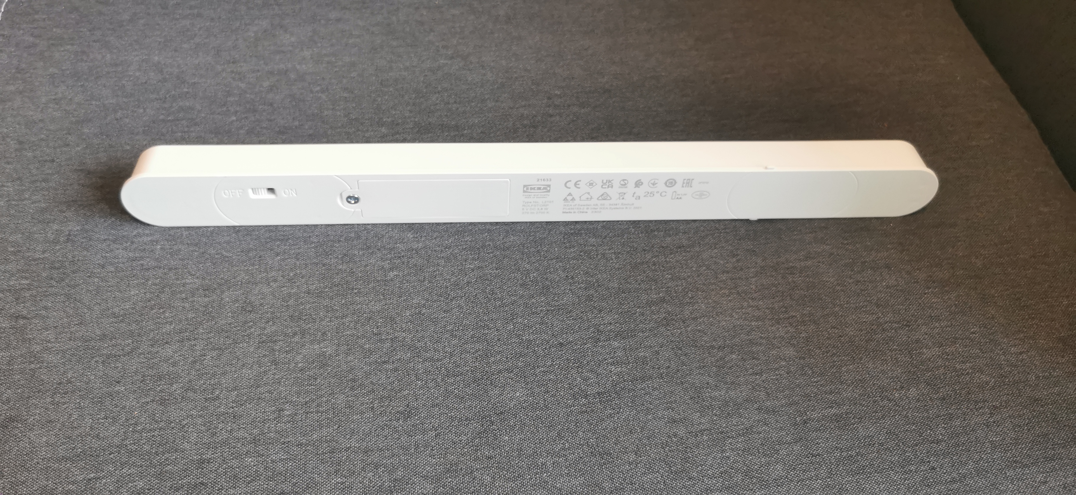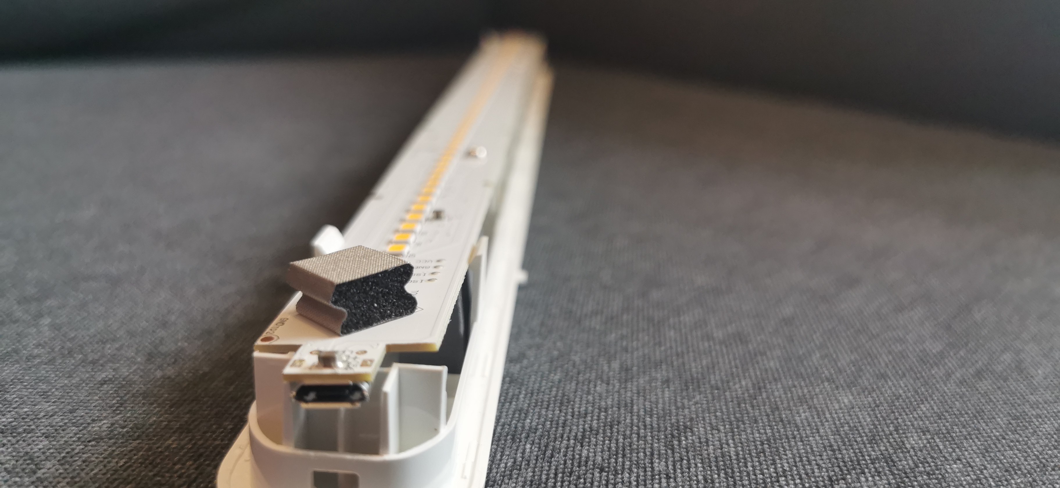
When I built a loft level into my room in the student dorm, I quickly noticed how one corner of my room, without a window and without a ceiling light, turned into a black hole. Luckily, a trip to IKEA was coming up anyway, and from then on two ROLFSTORP lamps for 7 € each defeated the darkness.
In everyday use, however, I soon found that switching on two lamps separately was too inconvenient for me. It would be much more practical if the lamps simply turned on together with the ceiling light.
First Steps
It’s what’s inside that counts
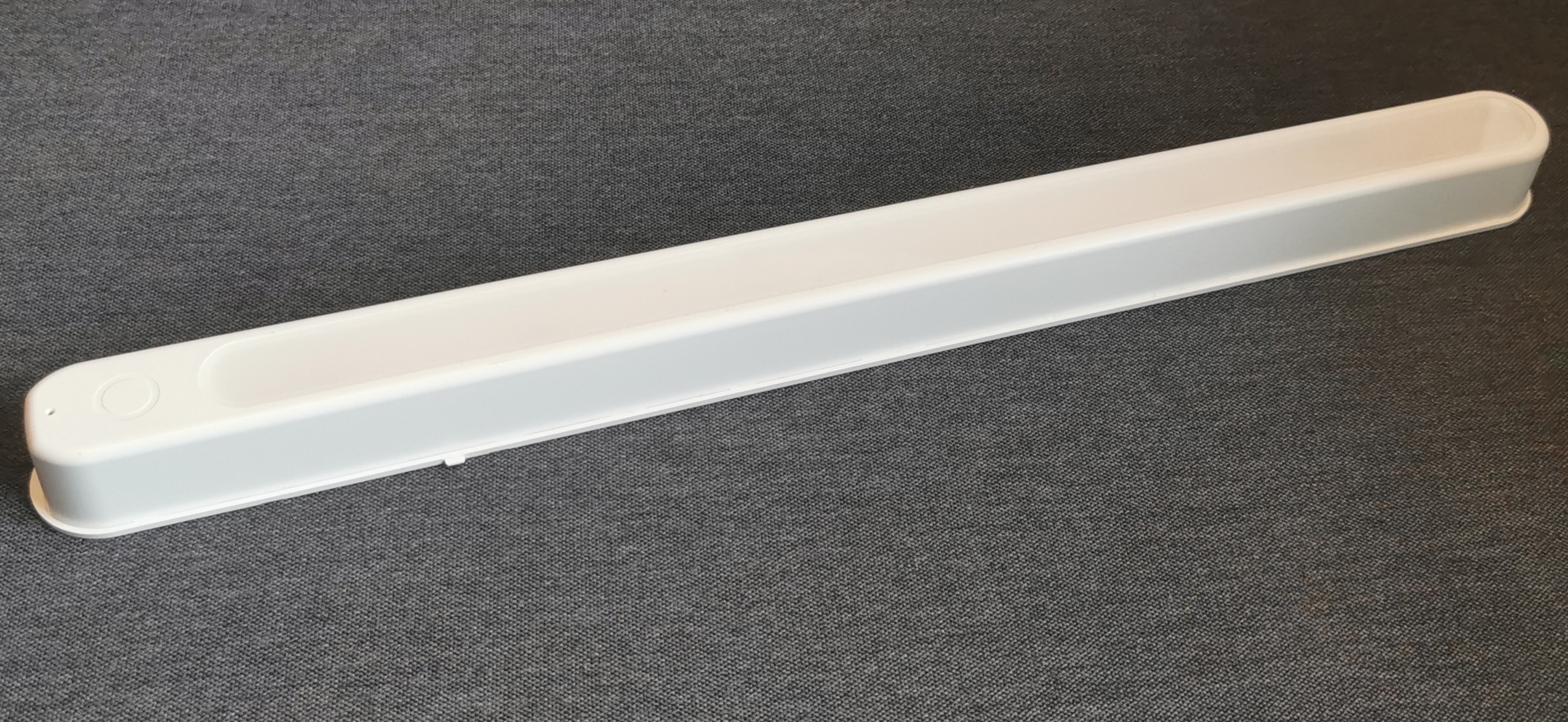
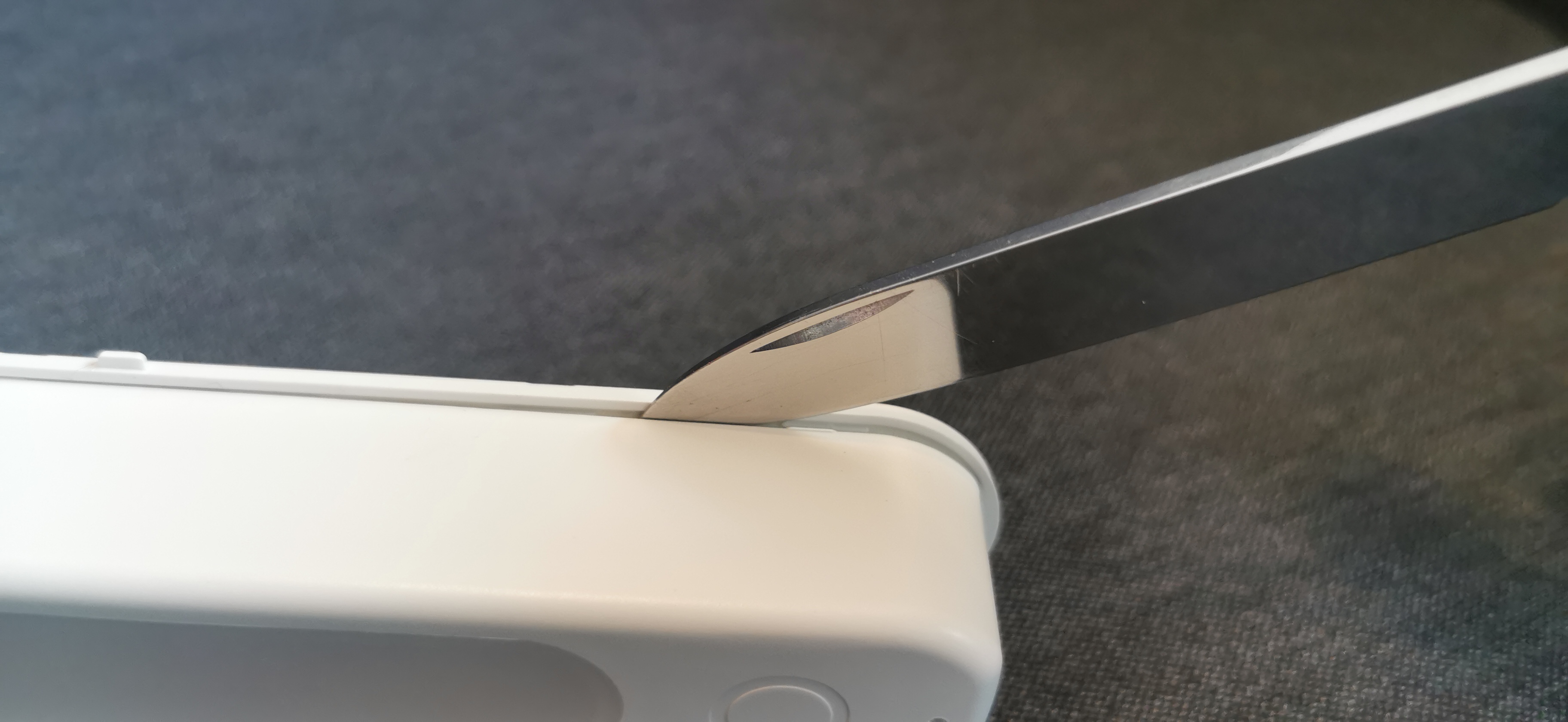
True to this motto, the first thing I did was open the lamp. The housing is held together by a few plastic clips. After opening the battery compartment, loosening the screw in there and removing all batteries, the diffuser cover can be unclipped. For me, this worked best by carefully prying it open at one of the ends with a knife.
After that, the cover can be removed completely and you can directly see the circuit board with the LEDs and, at one end, a silver foam cube with a conductive metal mesh. That is the electrode for the touch button.
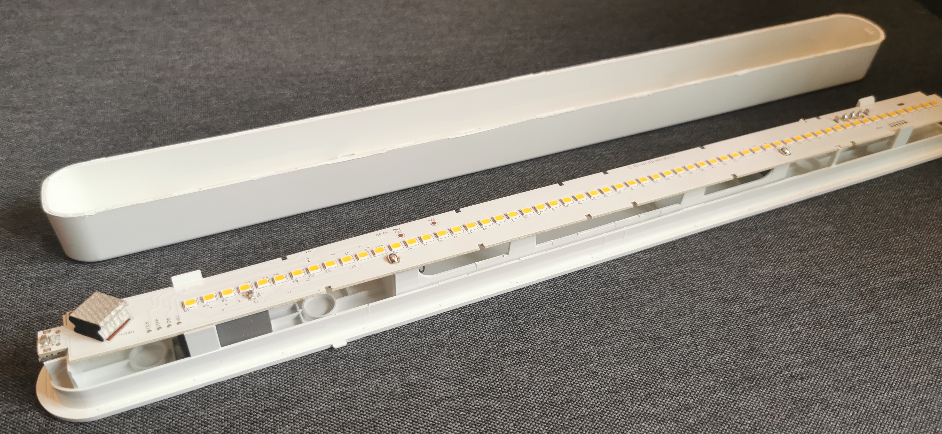
Up close, the touch sensor is even easier to see. The conductive mesh sits directly on a small pad of the circuit board; the foam underneath just ensures there is enough contact pressure against the housing when it is assembled.

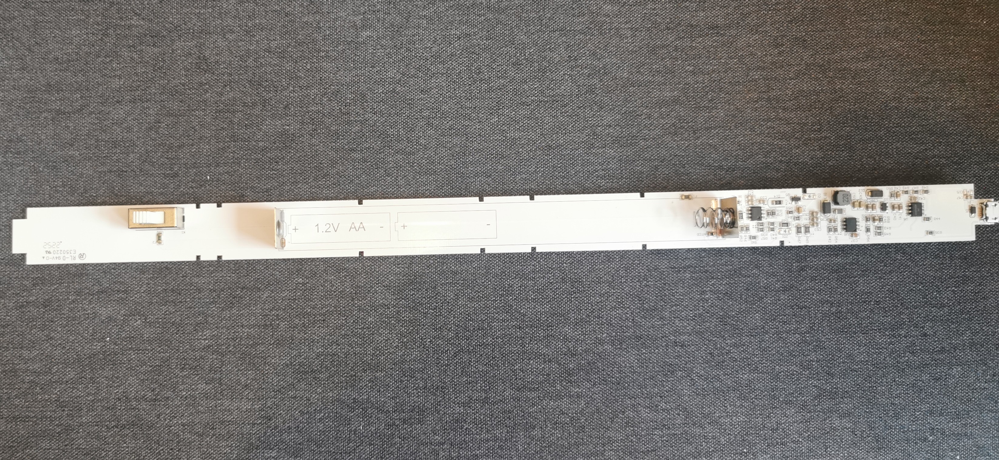
Next, the circuit board can be unclipped from its holders. On the back, next to the contacts for the two AA cells, you can already see all of the electronics next to the micro USB port on the PCB.
A Bit of Reverse Engineering
To modify the lamp in a sensible way, you first need a rough understanding of how the circuit works. Fortunately, it is fairly simple. Apart from the LEDs, all components sit on the back next to the micro USB port. The circuit essentially consists of three integrated circuits with their respective passive components around them.
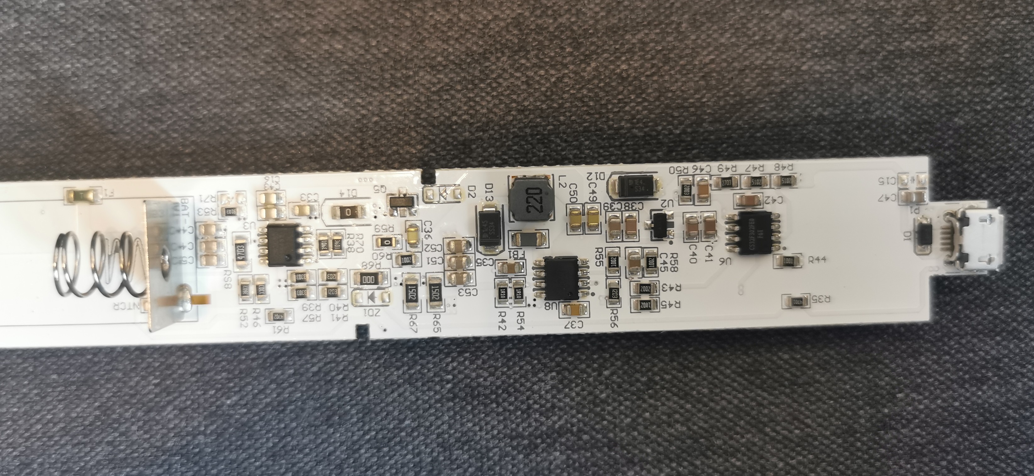
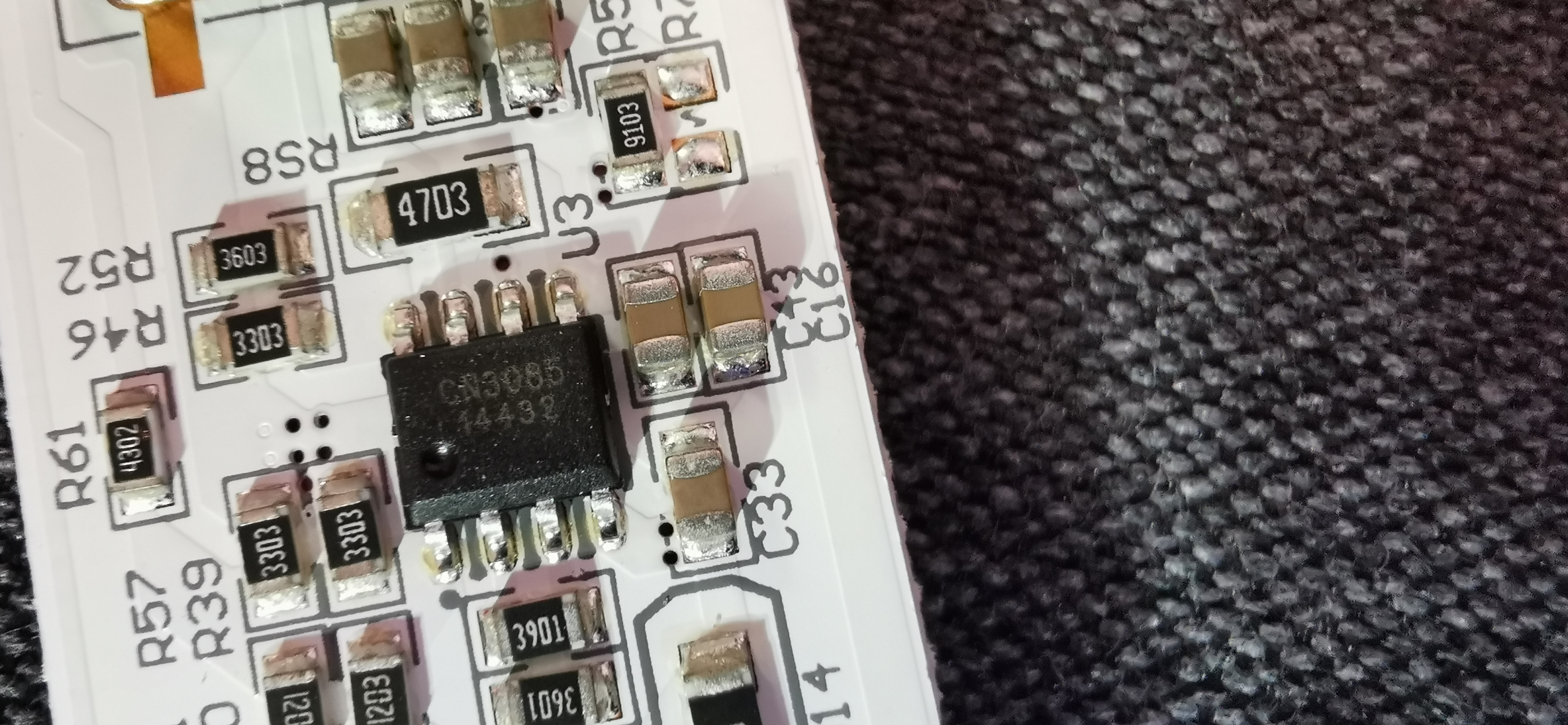
There are three ICs on the board: CS32F302FE0, MT7282 and CN3085.
The CS32F302FE0 sits where the trace to the touch pad arrives and presumably handles the capacitive evaluation of the touch signal as well as the actual control logic of the lamp (on, off, brightness levels). Despite quite some searching, I could not find an official datasheet for it; the chip seems to be a poorly documented MCU from a Chinese manufacturer. Conveniently, someone else had already tackled exactly this lamp and measured the behavior of the chip instead of just guessing: the forum thread on All About Circuits showed that one pin of the CS32F302FE0 outputs a different analog voltage depending on the selected brightness level; about 1.49 V, 0.92 V and 0.63 V were measured there for the different levels.
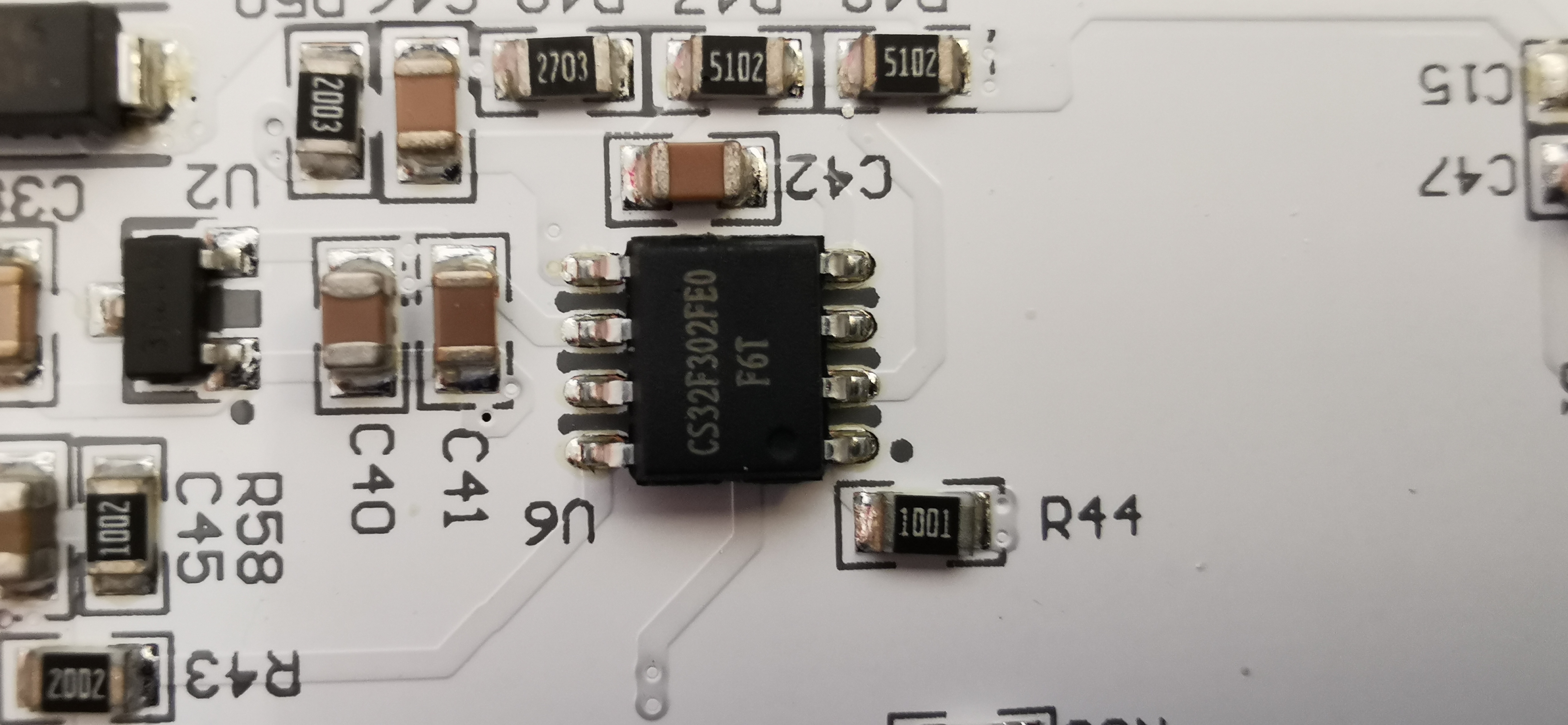
This voltage goes through a network of resistors, including R43 and R45, directly to the ADJ pin of the MT7282. According to its datasheet, this is a boost/buck boost/buck constant current driver for white LEDs with an input voltage range of 2.5 V to 40 V, which matches the inductor and the Schottky diode next to the chip. The ADJ pin controls the brightness, and according to the datasheet any voltage above about 1.6 V is clamped to 100 % current output. This also explains the different analog voltages of the CS32F302FE0: they control the LED driver and thus the brightness level.
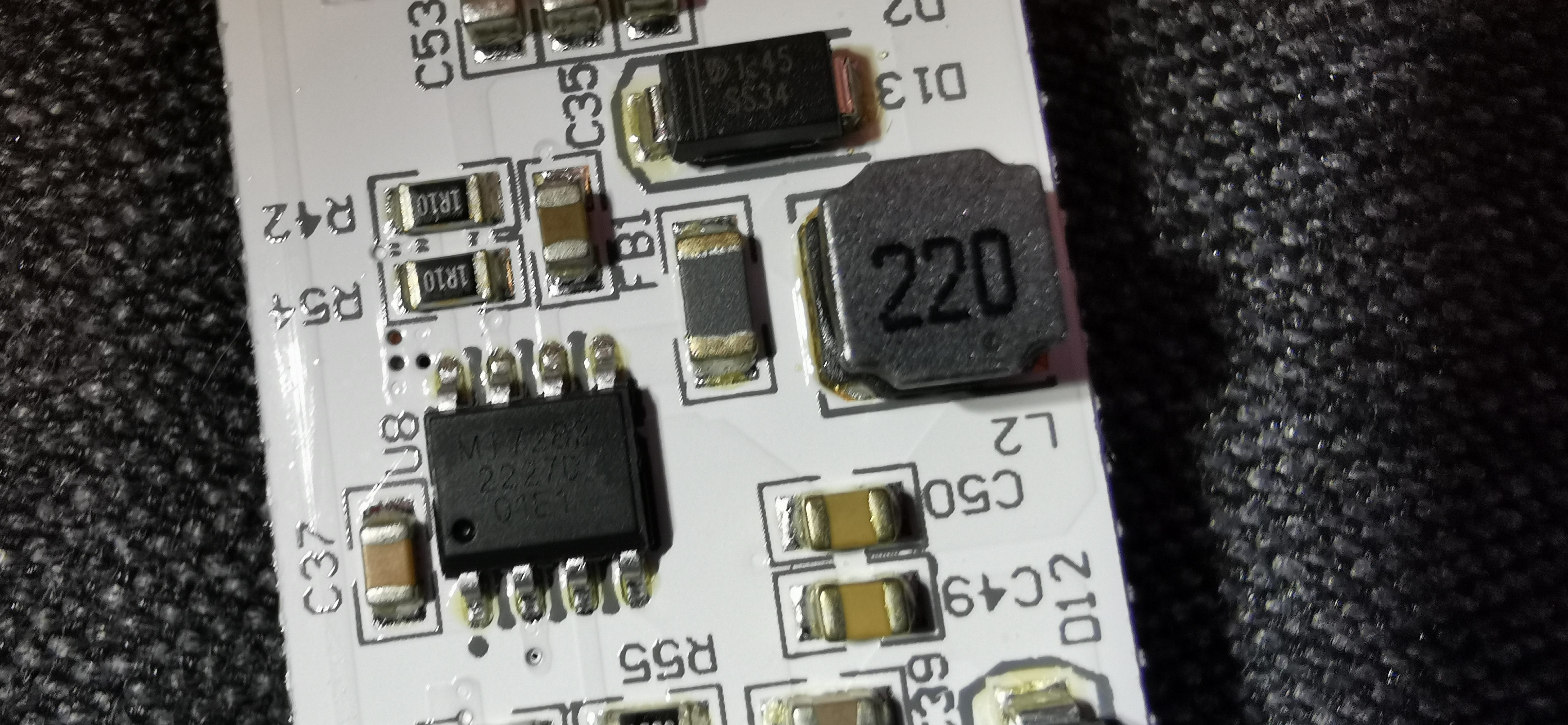
According to its datasheet, the third chip, the CN3085, is a charge controller for NiMH batteries with up to 1 A charging current, which fits the two built in AA cells well. For the modification you can safely ignore it, since in the end the lamp is permanently powered via USB.
Modification Guide
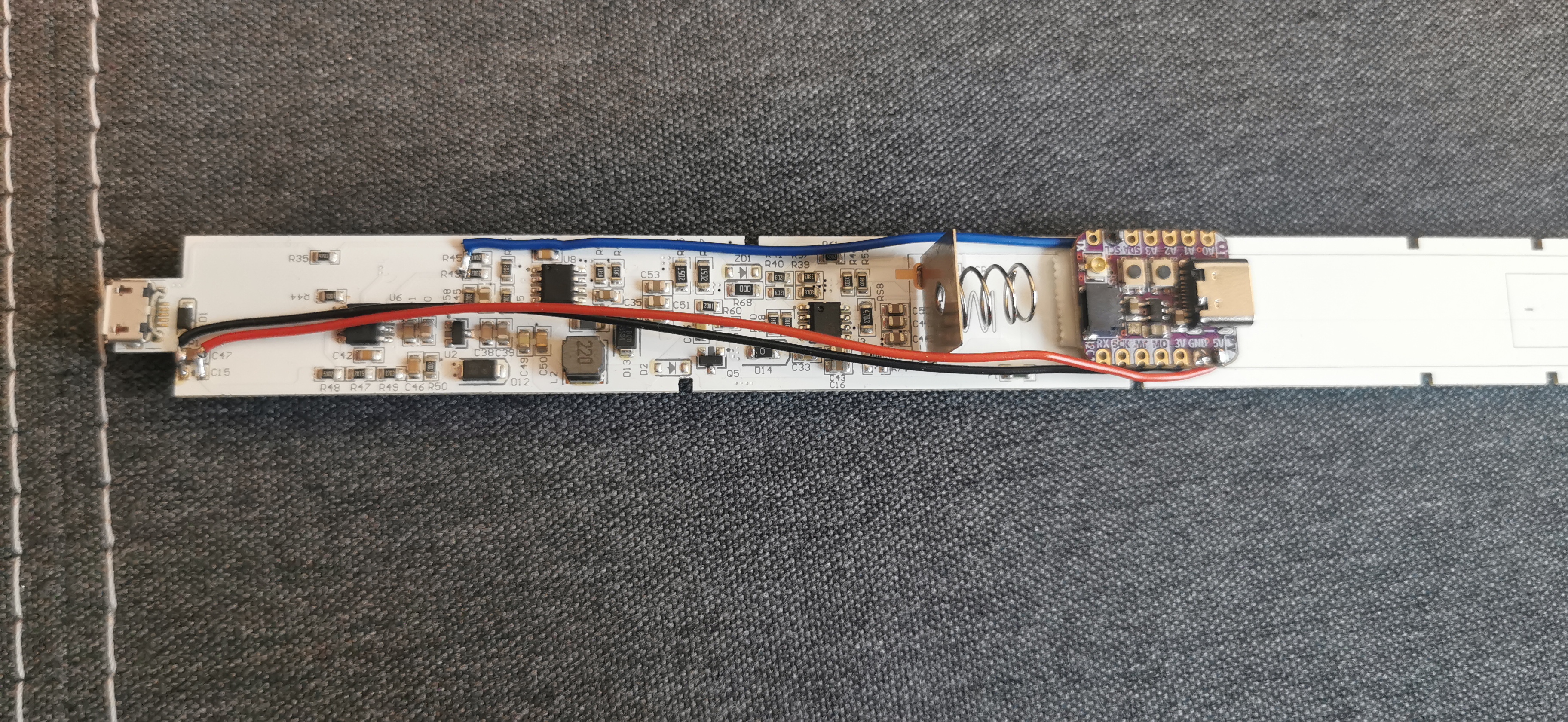
This is what the finished modified board should look like in the end, with the additional board and three wires to the main board.
Required Material
- Lamp
- Small ESP32 (I used an Adafruit QT Py ESP32 Pico; a Waveshare ESP32 C6 Zero or other boards should work just as well)
- Stranded wire
- Soldering iron
Soldering wires to the ESP32
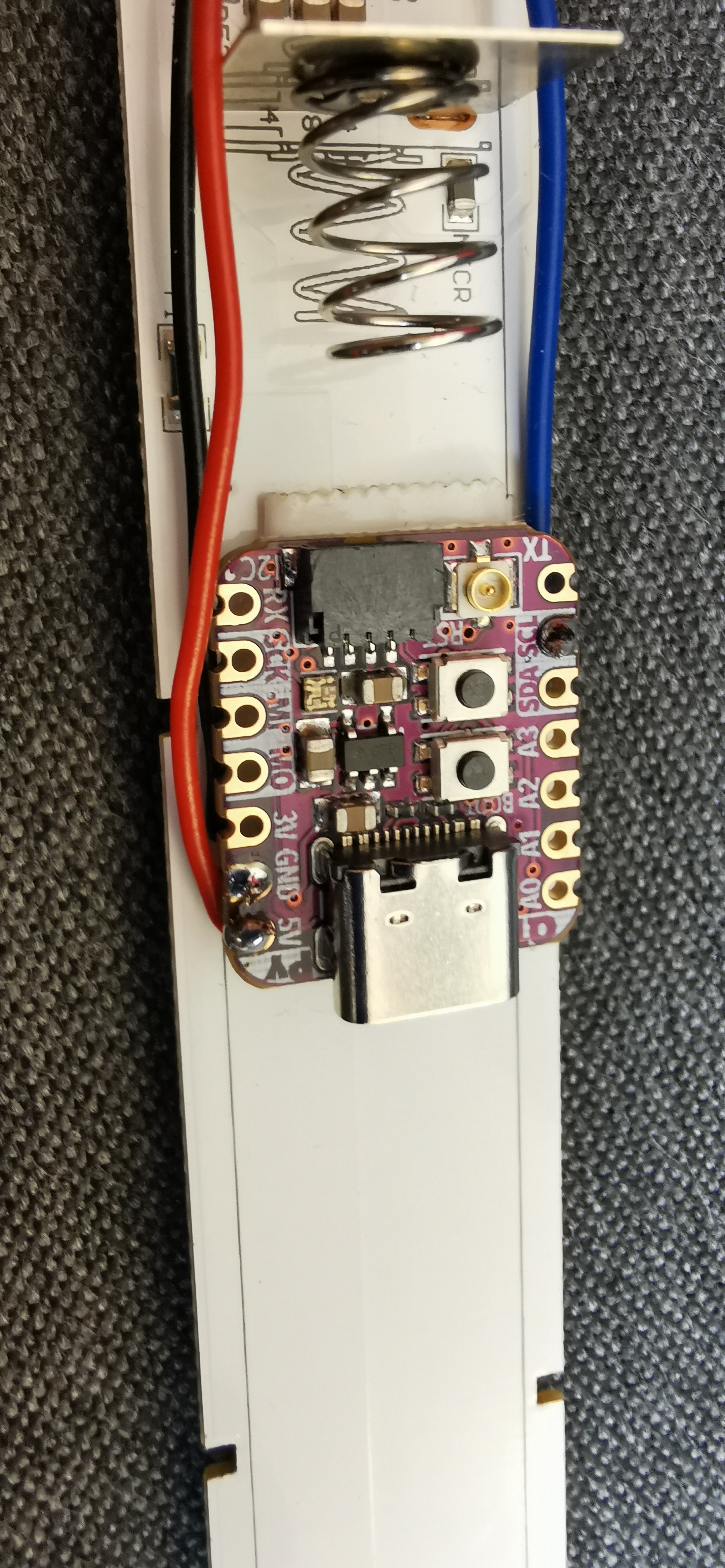
Solder one wire each to the 5V pin, the GND pin and a digital pin of the ESP32. In my case that was GPIO33.
Power supply
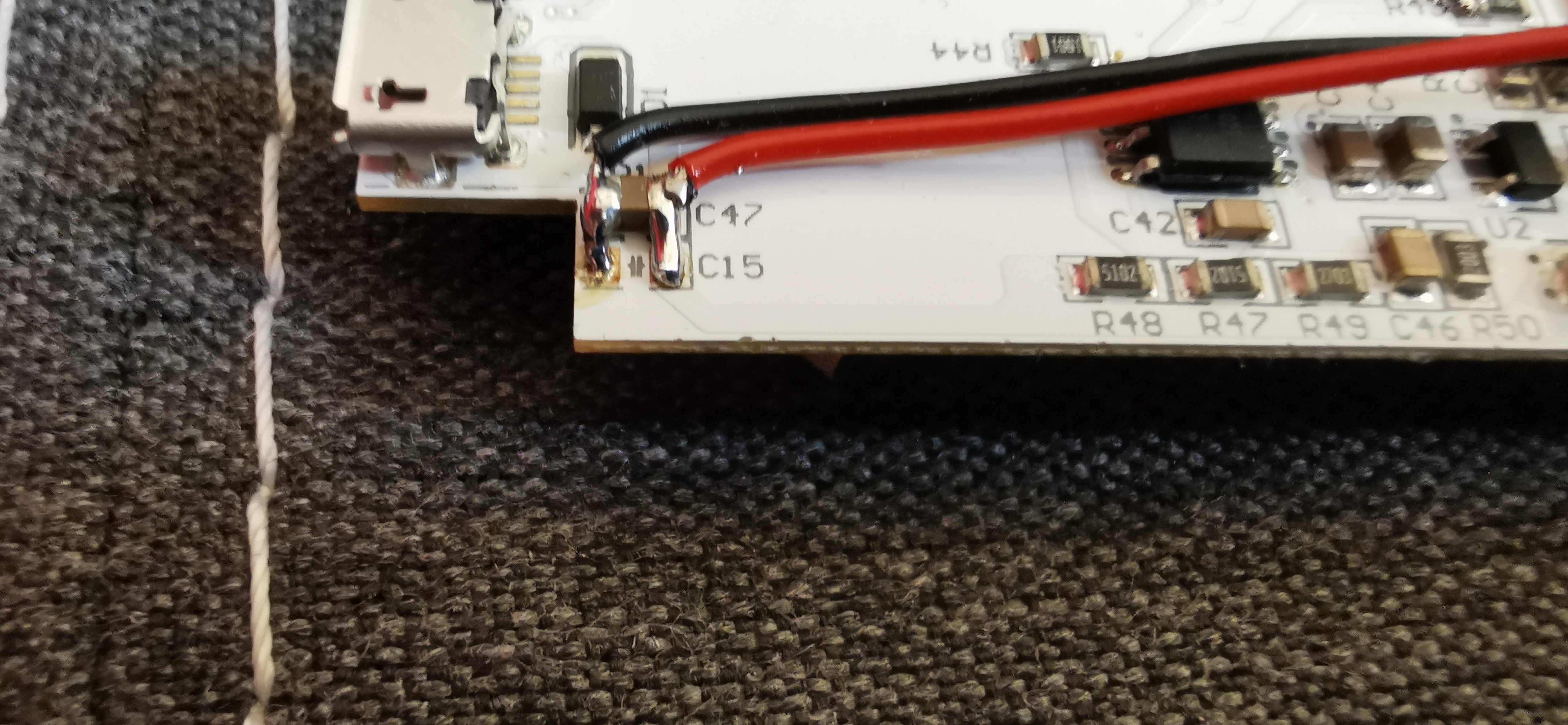
For the power supply I use the bypass capacitor right next to the micro USB port. As soon as the lamp is plugged in, the ESP32 is also powered through it. The wires are attached as follows:
Signal
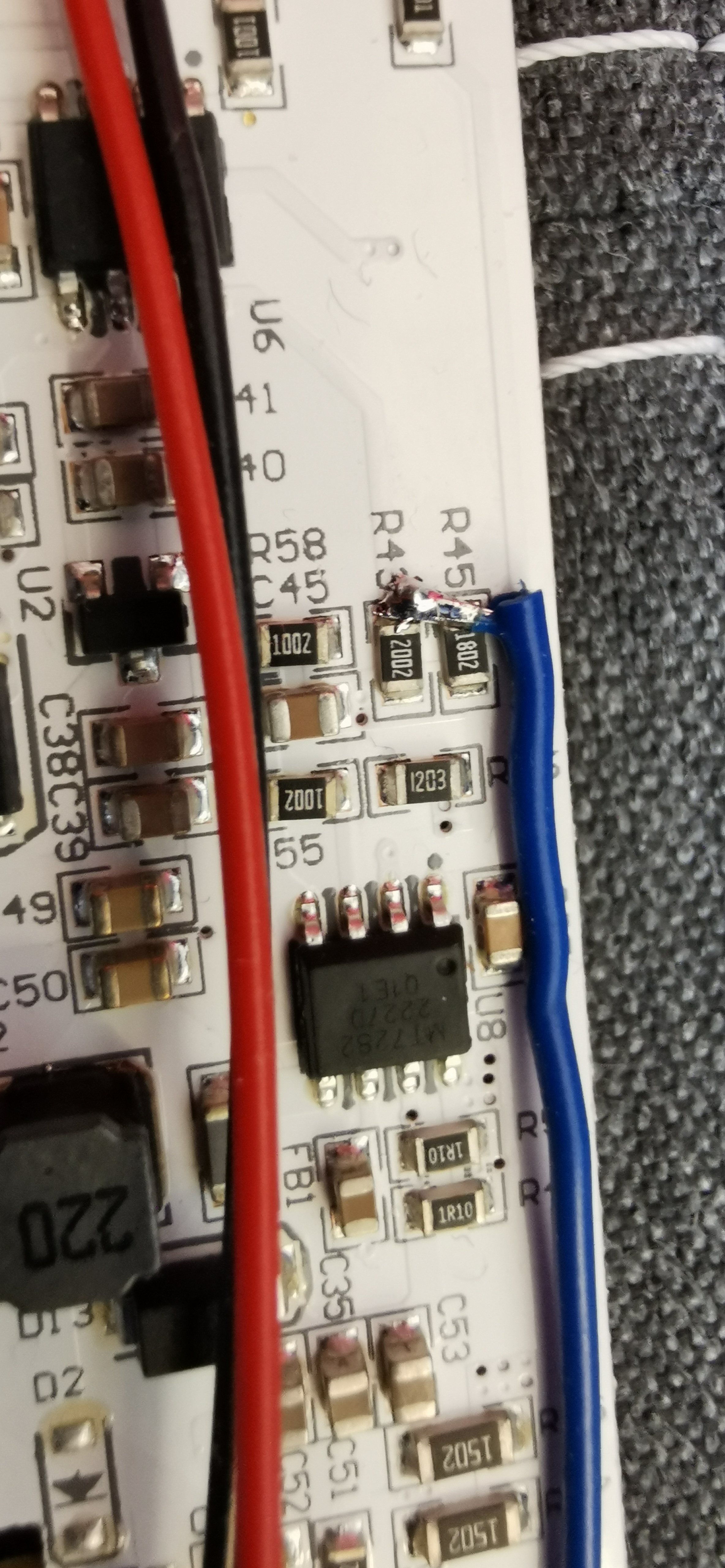
We connect the digital pin of the ESP32 on the left side to the junction of R43 and R45. These two resistors form the voltage divider described above, which normally passes the output signal of the CS32F302FE0 to the ADJ pin of the MT7282. The ESP32 now overrides this signal directly and thus takes over brightness control. The downside is that we lose the ability to use the touch sensor directly, since the ESP32 overrides the original signal. If you want to keep using the touch button in parallel, the forum thread linked above describes an alternative approach using an additional pullup resistor instead of directly overriding the signal.
Making it robust
Afterwards, the ESP32 can be glued directly into the battery compartment, there is enough space there. Battery operation is irrelevant for me anyway, since I want to run the lamp permanently from a power supply. The wires can then be glued down as well, so that nothing is dangling around loosely during reassembly.
Programming
Now the ESP32 can be connected to the PC via USB. For the software I chose ESPHome. It lets you create firmware for common microcontrollers using just a YAML configuration file, without writing any code yourself, and integrate it directly into Home Assistant. For my purposes, ESPHome’s monochromatic light is enough: it turns a simple brightness output into a dimmable lamp that can be programmed and integrated into Home Assistant with little effort.
Then everything can be reassembled and tested. The ESP32 should then show up in Home Assistant, where it can be dimmed and switched together with the ceiling light.
Conclusion
Even though it has been almost two years since I modified the lamps, it has stuck in my mind as a nice little project for an evening. For me it ticked all the boxes: quick to do, cheap, practical, and it has been running flawlessly ever since.