In summer you can usually find me as a leader at the boys’ summer camp at Mühlnickelweiher run by CVJM Bayreuth (the German YMCA). We have a brilliant kitchen team there that impresses everyone again every year. You look forward to the food half a year in advance and still miss it half a year afterwards.
Since there is no mains power and no fixed gas connection, we cook with propane from bottles. We have four 33 kg bottles and one medium sized 11 kg bottle for that, which also supply a few gas fridges. Since these can only achieve a limited temperature difference to their surroundings, they run as either fridges or freezers depending on the outside temperature. Especially with the big bottles it is hard to guess how much gas is left. Every now and then one runs empty right in the middle of cooking, just when nobody is around who can change the bottles. It is similar with the drinking water, which comes from a large stainless steel tank on a trailer. There too you have to climb up every time and look how much is left.
So it would be really nice to see at a glance where how much is left. That is how the idea of a compact, clear display showing all fill levels came about. The project ended up taking quite a few evenings, so I decided to write it up as a small series:
- Tent pole holder (this article)
- The sensor: teardown, reverse engineering and current measurement
- The Arduino software and first tests
A real world test at the camp is still missing, it will follow next August.
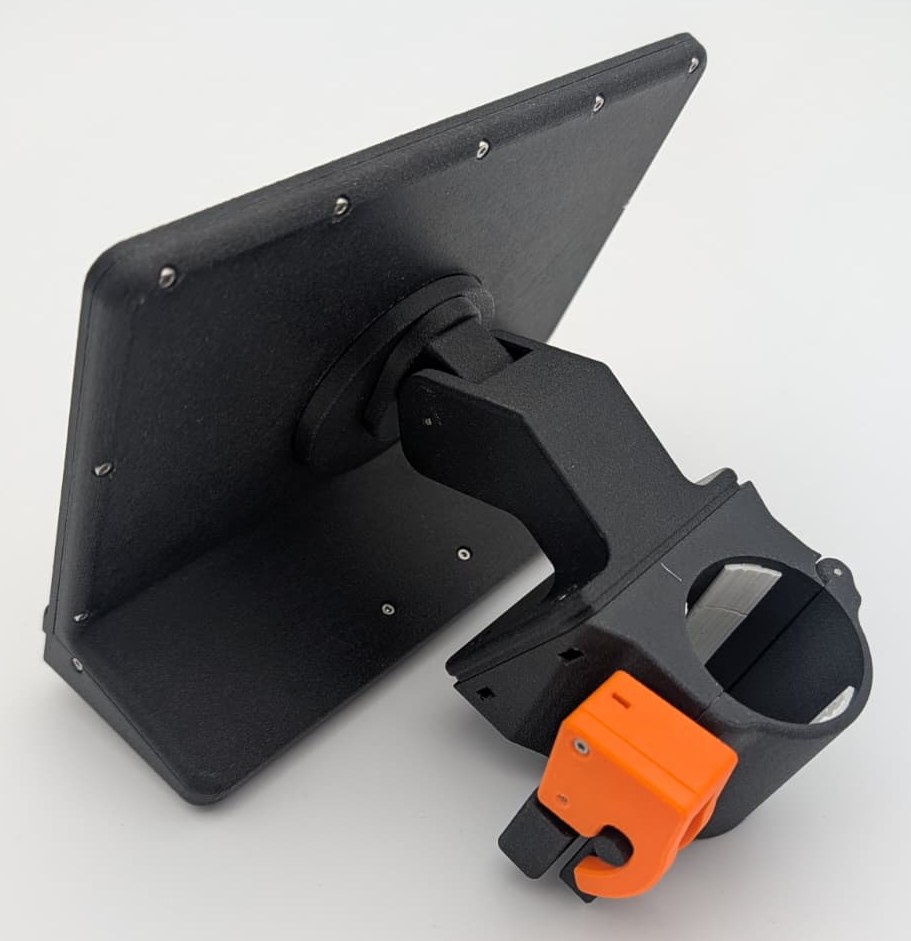
The display itself is a 7.5 inch ePaper in the same case as my room display. That article describes in detail how the case and the magnetic holder are built and how long the battery lasts. This part is about how the display gets onto the pole in the kitchen tent.
The Pole
Our kitchen tent has aluminium leg tubes with 40 mm diameter and 1.5 mm wall thickness. They are not vertical but tilted by 19.5° from vertical. The tent fabric is directly behind the tube, so there is hardly any room there.
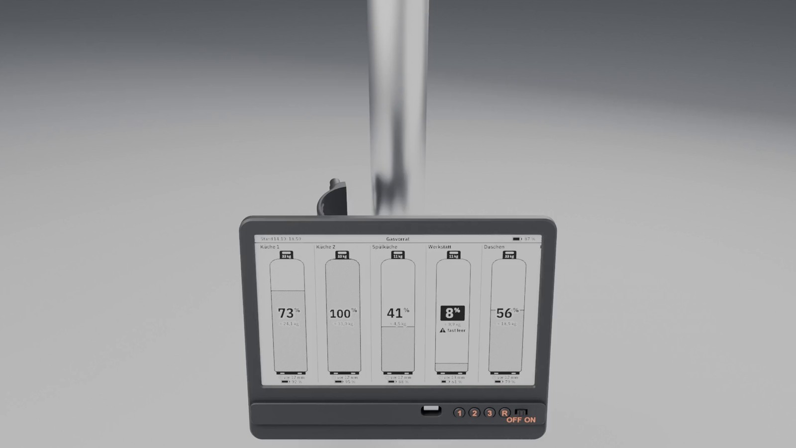
For the holder to be as easy to use as possible, it was important to me that it
- can be mounted and removed without tools, since the tent is set up anew every year
- needs no modifications to the tent
- clamps firmly, so nothing wobbles or works loose even in wind and storms
- keeps the display vertical despite the slanted pole and lets me adjust its tilt
- lets the display come off quickly for charging
First Attempt: a Snap On Clip
At the camp we already use 3D printed clips to quickly attach the cables for the lights to the poles. So my first idea was to reuse the geometry of these clips. A test print showed, however, that the bare clips have little grip and can be twisted on the tube, and that the planned ABS GF is too stiff for them to work well. So back to CAD.
The Solution: Hinged Shell with Cam Lever
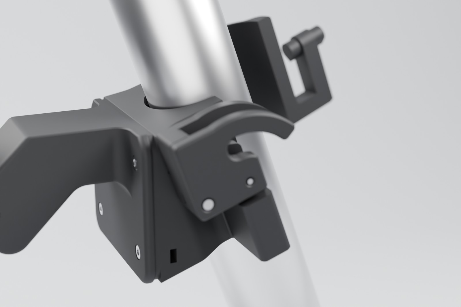
The second version works like a quick release. It consists of three parts:
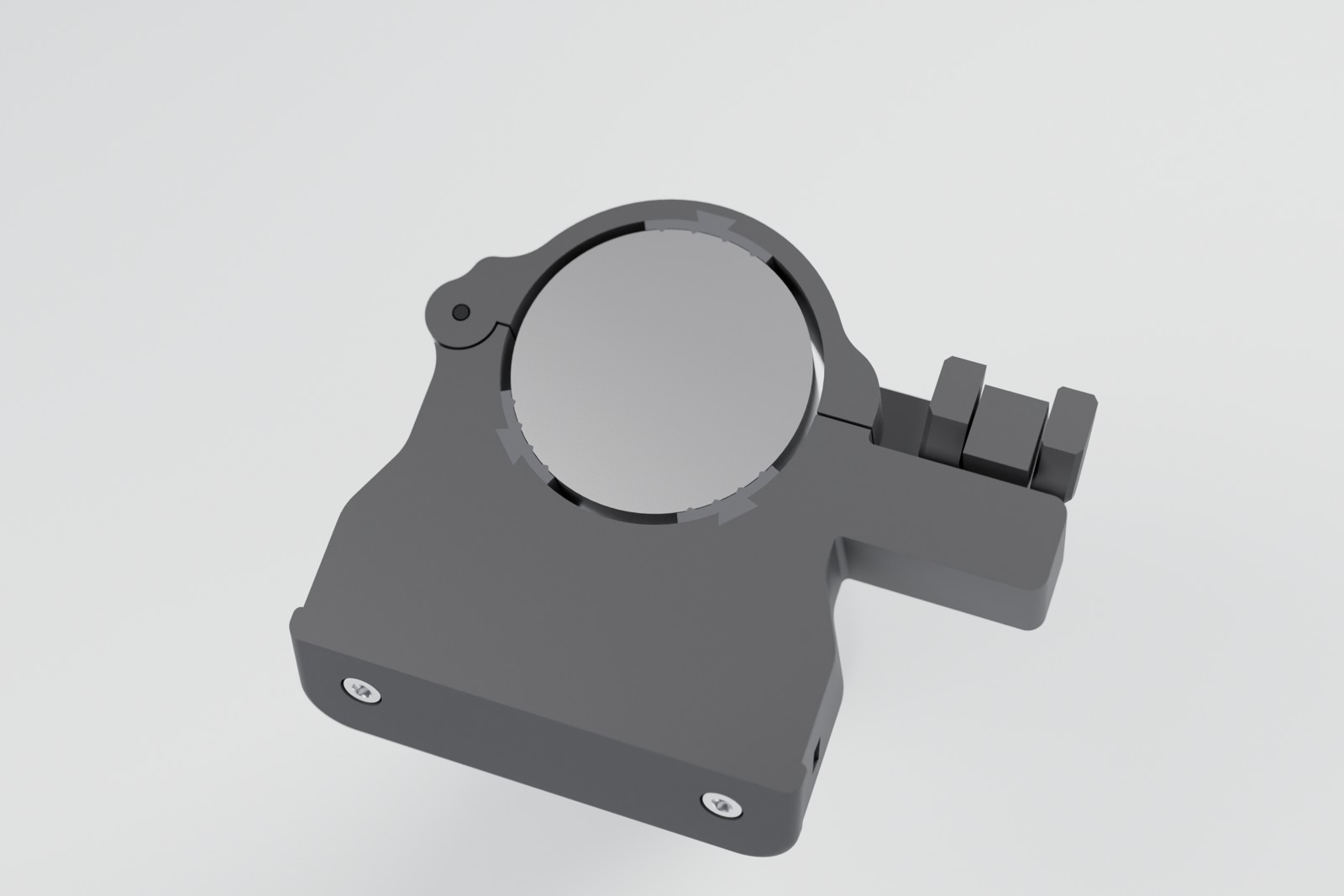
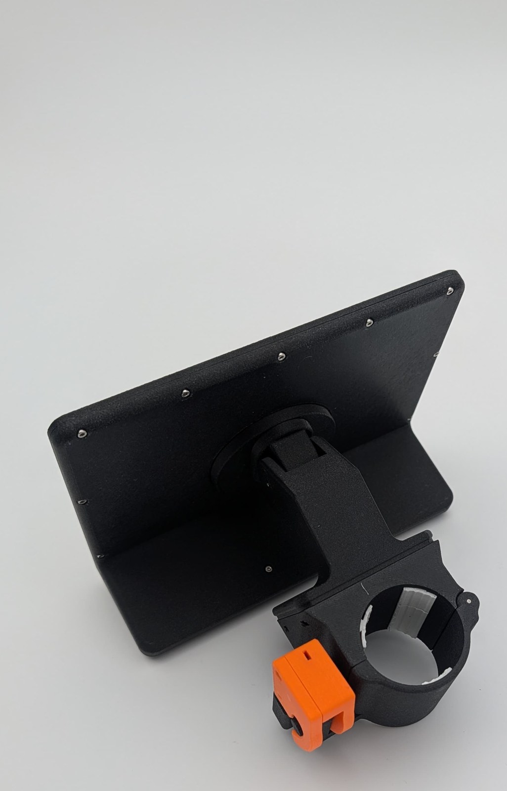
- Saddle with wedge: At the front, a half shell rests against the tube. It is one piece with a 19.5° wedge that compensates for the tilt of the pole. The arm is attached to the wedge face with four M3 screws.
- Hinged shell: Behind the tube sits a second half shell, hinged to the saddle. A steel pin with 2 mm diameter and 50 mm length serves as the hinge axle. Behind the tube the shell is only 4.5 mm thick so it fits between tube and tent fabric.
- Cam lever: A bracket made of two cheeks reaches over a pin on the shell and pulls it against the tube via a cam. The cam has 2.5 mm eccentricity, which gives about 1.75 mm of travel. The lever goes about 10° past dead centre and therefore stays closed by itself.
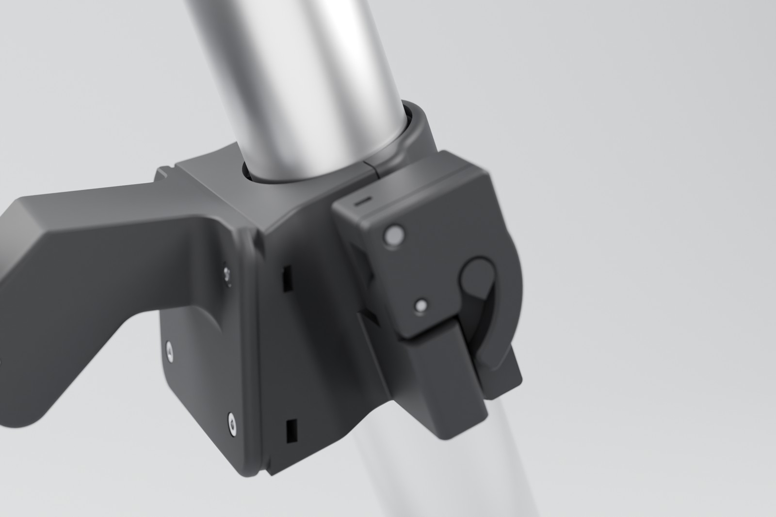
Both half shells have TPU inserts. They are not glued but held in place by a dovetail with 60° flanks, and have four longitudinal ribs. With 0.4 mm interference on the tube diameter, they clamp the tube firmly without scratching it.
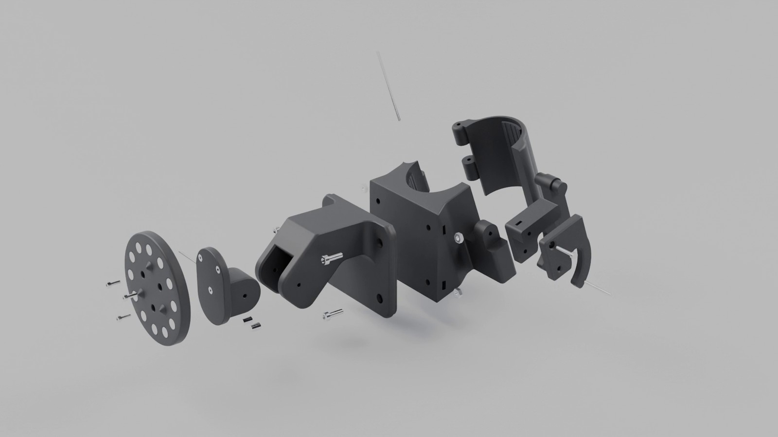
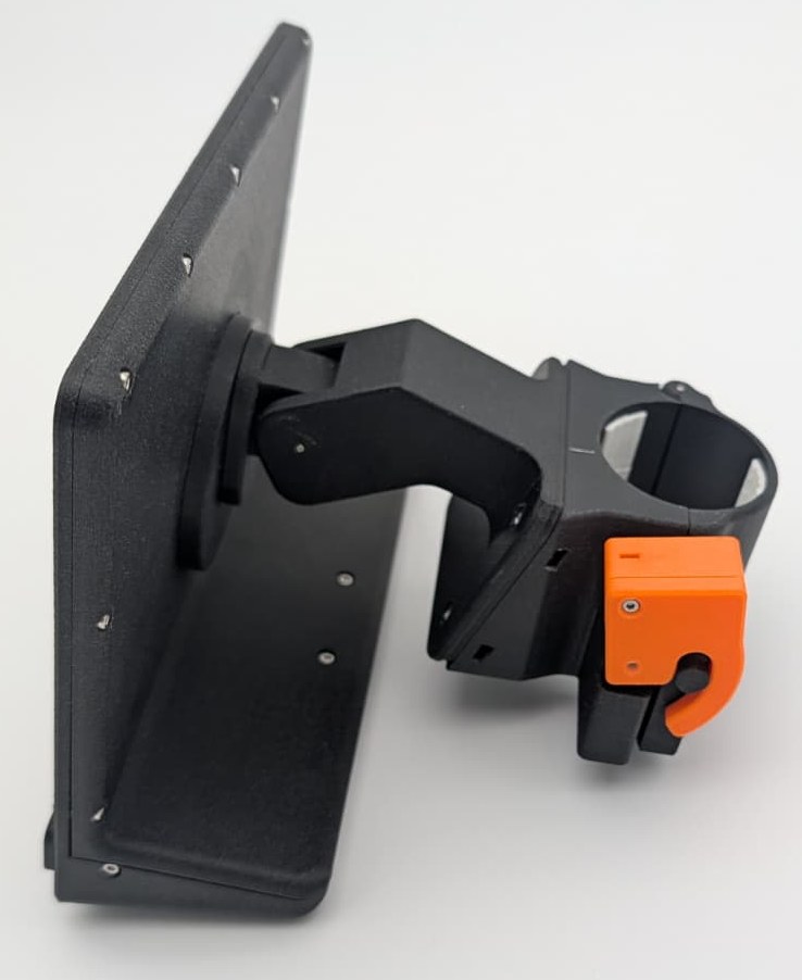
Between clamp and display sits the same arm with detent joint and magnetic disc as on the wall holder of the room display, just with a slightly thicker plate for the clamp. The joint clicks from −45° to +45° in 15° steps. In the middle position the display hangs exactly vertical on the slanted pole.
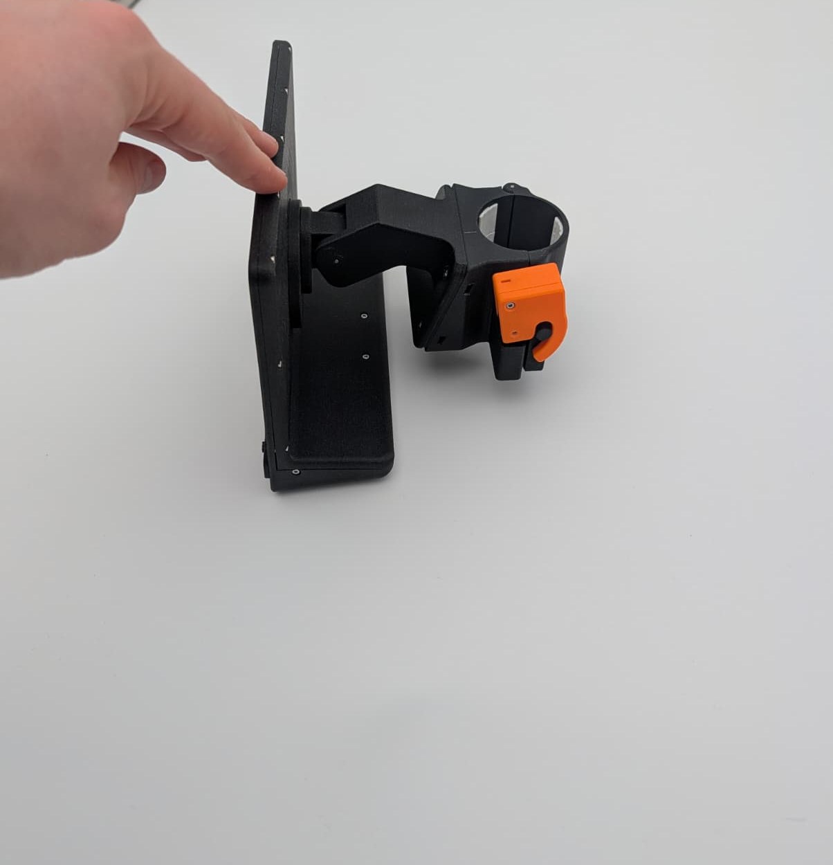
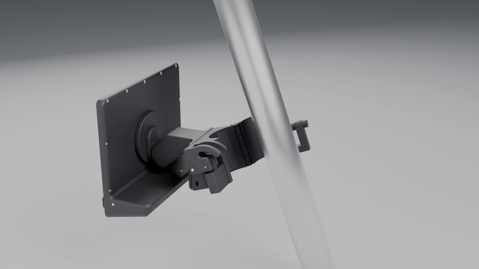
The display holds on the holder disc via twelve magnet stacks, and three cones centre it. For charging, you simply pull it off and the holder stays on the pole. At home on the wall holder this has already proven itself: the connection is very firm, comes off with one move, but does not come loose by accident.
Designed in FreeCAD
I designed everything in FreeCAD. The case is built parametrically there, so its dimensions are easy to adjust. Saddle, hinged shell and cam lever, on the other hand, are included in the project as fixed solids and can only be changed to a limited extent.
Material
For one complete device for the tent, i.e. display with case and pole holder:
| Part | Quantity |
|---|---|
| TRMNL 7.5" (OG) DIY Kit (display, XIAO ePaper board with XIAO ESP32 S3 Plus, 2000 mAh battery) | 1 |
| Socket head screw M2×4 (DIN 912) | 6 |
| Socket head screw M2×6 | 13 |
| Socket head screw M2×8 | 3 |
| Socket head screw M2×12 | 2 |
| M2 nut | 24 |
| Socket head screw M3×10 (ISO 4762) | 4 |
| M3 nut | 4 |
| Neodymium magnet 6 × 2 mm | 48 |
| Bambu Lab ball spring plunger 5 × 6 mm (FB004) | 2 |
| Steel pin 2 × 30 mm (joint) | 1 |
| Steel pin 2 × 50 mm (hinge) | 1 |
| Steel pin 2 × 20 mm (cam lever) | 1 |
| Rubber foot 8 × 2 mm (optional, only for standing) | 4 |
| Filament ABS GF black and orange, Bambu TPU for AMS |
On top of that come the level sensors, more on those in part two.
Assembly
- Insert the M3 nuts into the side slots of the saddle and screw the saddle to the arm with four M3×10.
- Open the hinged shell by about 90°, slide it into the hinge eyes from the side and press in the 50 mm pin from the top.
- Place the two cheeks of the cam lever around the centre lug, push the 20 mm pin through and screw cheek B to the grip bar with an M2×12.
- Assemble joint and holder disc as on the wall holder, see room display.
At the tent it then works without tools: open the lever, open the shell, put the saddle against the tube from the inside, close the shell behind the tube, hook the bracket over the pin and flip the lever over. Finally, put the display on.
Build Your Own
I printed all parts in ABS GF, the TPU inserts are printed directly in the AMS. All print settings are saved in the Bambu Studio project, where the parts are already arranged on the plates. The pole holder parts are printed standing on their end face, i.e. with the tube axis vertical. A few painted on supports can help under the overhanging hinge eyes.
If your printer does not have a (good) multi material system or tool changer, you can also print the TPU inserts separately and then press them into the dovetail groove with a lot of force.
- Bambu Studio project with all parts and print settings (ABS GF and TPU)
- Pole holder parts as STL and 3MF with assembly instructions
- FreeCAD project with case and pole holder
- Case and wall holder are also in the room display article
The holder is licensed under CC BY-NC-SA 4.0. This means you may build, modify and share it free of charge, as long as you credit me as the creator, do not use it commercially and share your own modifications under the same license.
If you have questions or need other file formats, feel free to write to me: loading …
Conclusion
The detour via the clip was worth it: the hinged shell with cam lever goes onto the pole in seconds without tools and keeps the display vertical despite the slanted pole. Whether it also holds up at the real camp, with wind, rain and a lot of hustle in the kitchen, will show in August. There will be an update here then.
The next part is about the actual heart of the project: the sensor under the gas bottle, which I took apart and whose radio protocol I decoded.